Removed text is struck through; added text is highlighted.
XLog is a compact ECU logger with internal satellite positioning, inertial sensors and a rechargeable battery. It does not include an integrated dashboard display. For the range overview see AiM in-car dataloggers.
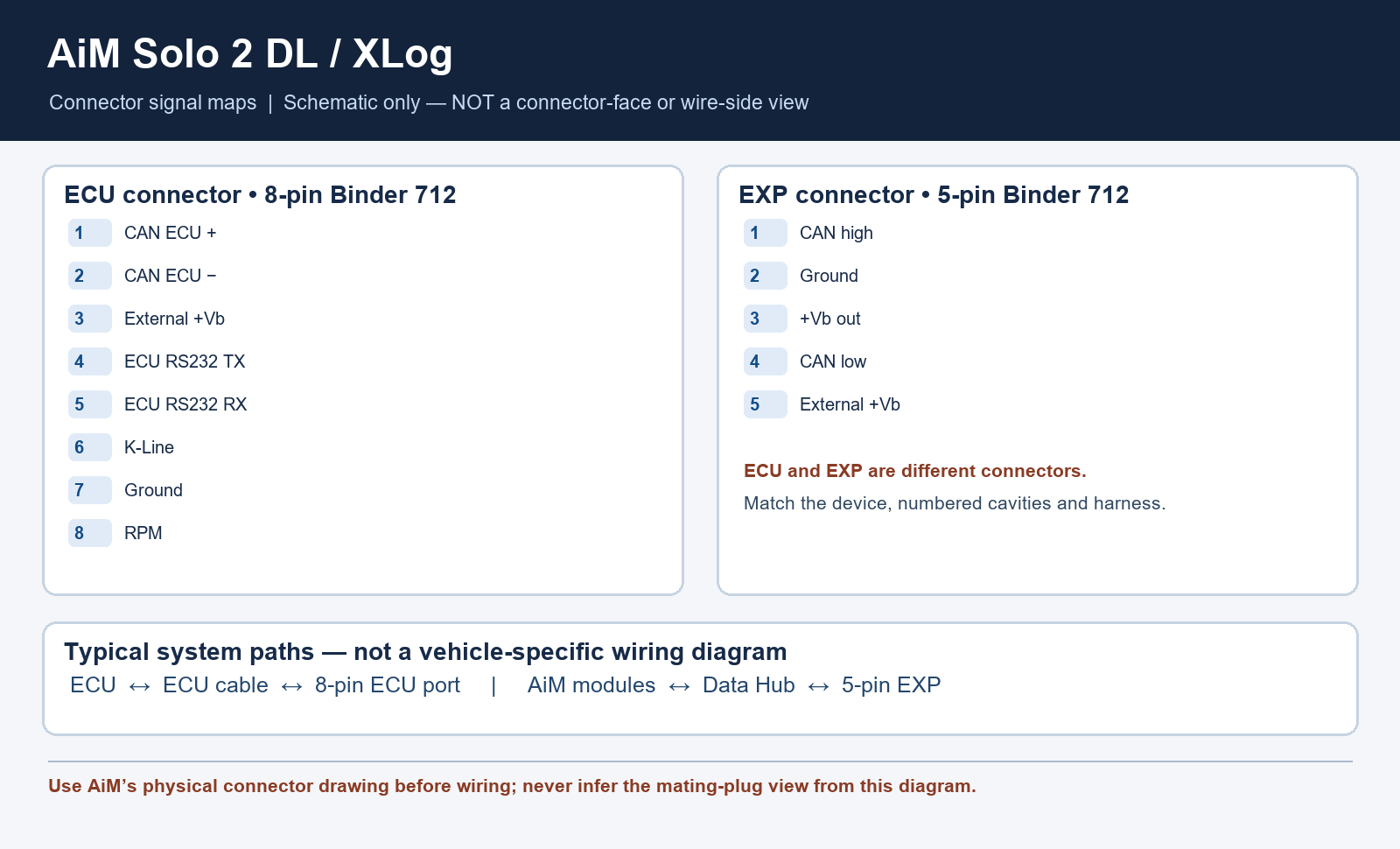
XLog and Solo 2 DL functional connection paths; original Tuning Wiki illustration based on AiM documentation. Schematic diagrams do not show physical connector positions unless explicitly labelled.
Use the specified CAN/RS232, CAN/K-Line OBD or RPM cable for the installation. An AiM expansion module is required when additional channels are needed; select supported hardware and check external power arrangements.
Choose the correct model-specific lead and configure the ECU protocol in Race Studio 3. A connector shape alone does not establish vehicle compatibility. Confirm every cavity number, signal level, ground, power source and electrical limit in the linked AiM documentation before wiring; diagrams are from the device view or a conceptual schematic as stated. Secure the loom and make connections with power disconnected.
Software and further reading
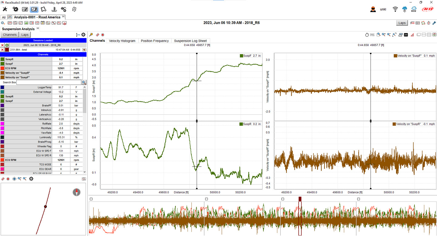
Race Studio 3 Analysis example showing suspension traces; actual channels depend on the device and connected sensors. Image: AiM, reproduced with permission; manufacturer source.
Analysis and download: AiM's XLog guide describes downloading stored sessions into Race Studio 3 and opening them in Race Studio Analysis for graphs and track views. AiM model guidance. Download the Windows software from AiM Race Studio 3 software downloads. For capabilities and compatibility see AiM data-log analysis software.
Use AiM Race Studio 3 to configure supported devices and analyse recorded sessions. Check the specific ECU protocol and cable before connection; not every source exposes every channel. Manufacturer references: model documentation.
Rendered revisions
Open each version to inspect formatting, tables and photographs.
Revision 2: AiM XLog
XLog is a compact ECU logger with internal satellite positioning, inertial sensors and a rechargeable battery. It does not include an integrated dashboard display. For the range overview see AiM in-car dataloggers.
AiM identifies female Binder 712 connectors in external device view. The ECU socket has eight pins and is not the seven-pin ECULog socket.
Expansion, 5-pin Binder 712 female
Pin
Function
1
CAN high / CAN+ expansion
2
Ground
3
+Vb out
4
CAN low / CAN− expansion
5
+Vb external
ECU, 8-pin Binder 712 female
Pin
Function
1
CAN ECU+
2
CAN ECU−
3
+Vb external
4
ECU RS232 TX
5
ECU RS232 RX
6
K-Line
7
Ground
8
RPM
Wiring and installation
XLog and Solo 2 DL functional connection paths; original Tuning Wiki illustration based on AiM documentation. Schematic diagrams do not show physical connector positions unless explicitly labelled.
Use the specified CAN/RS232, CAN/K-Line OBD or RPM cable for the installation. An AiM expansion module is required when additional channels are needed; select supported hardware and check external power arrangements.
Choose the correct model-specific lead and configure the ECU protocol in Race Studio 3. A connector shape alone does not establish vehicle compatibility. Confirm every cavity number, signal level, ground, power source and electrical limit in the linked AiM documentation before wiring; diagrams are from the device view or a conceptual schematic as stated. Secure the loom and make connections with power disconnected.
Software and further reading
Race Studio 3 Analysis example showing suspension traces; actual channels depend on the device and connected sensors. Image: AiM, reproduced with permission; manufacturer source.
Use AiM Race Studio 3 to configure supported devices and analyse recorded sessions. Check the specific ECU protocol and cable before connection; not every source exposes every channel. Manufacturer references: model documentation.
Revision 2: AiM XLog
XLog is a compact ECU logger with internal satellite positioning, inertial sensors and a rechargeable battery. It does not include an integrated dashboard display. For the range overview see AiM in-car dataloggers.
AiM identifies female Binder 712 connectors in external device view. The ECU socket has eight pins and is not the seven-pin ECULog socket.
Expansion, 5-pin Binder 712 female
Pin
Function
1
CAN high / CAN+ expansion
2
Ground
3
+Vb out
4
CAN low / CAN− expansion
5
+Vb external
ECU, 8-pin Binder 712 female
Pin
Function
1
CAN ECU+
2
CAN ECU−
3
+Vb external
4
ECU RS232 TX
5
ECU RS232 RX
6
K-Line
7
Ground
8
RPM
Wiring and installation
XLog and Solo 2 DL functional connection paths; original Tuning Wiki illustration based on AiM documentation. Schematic diagrams do not show physical connector positions unless explicitly labelled.
Use the specified CAN/RS232, CAN/K-Line OBD or RPM cable for the installation. An AiM expansion module is required when additional channels are needed; select supported hardware and check external power arrangements.
Choose the correct model-specific lead and configure the ECU protocol in Race Studio 3. A connector shape alone does not establish vehicle compatibility. Confirm every cavity number, signal level, ground, power source and electrical limit in the linked AiM documentation before wiring; diagrams are from the device view or a conceptual schematic as stated. Secure the loom and make connections with power disconnected.
Software and further reading
Race Studio 3 Analysis example showing suspension traces; actual channels depend on the device and connected sensors. Image: AiM, reproduced with permission; manufacturer source.
Use AiM Race Studio 3 to configure supported devices and analyse recorded sessions. Check the specific ECU protocol and cable before connection; not every source exposes every channel. Manufacturer references: model documentation.