A dynamometer controller regulates the load applied to the engine or vehicle and may also operate the throttle and record test data. It does not determine the dyno type by itself: an electronic controller can command an eddy-current brake, a water valve, a hydrostatic system or an electrical machine, each with different physical limits. Start with Dynamometers.

Manual and older controls
A basic manual system uses an operator, speed indication, a torque display and a valve or electrical field control. The operator changes the load while observing the engine. Mechanical linkages, separate analogue indicators and chart recorders can be found on older installations. Manual control can perform a steady test, but maintaining a repeatable target depends heavily on operator response.
Automatic feedback is not exclusively digital or new. A historical University of Edinburgh review describes a 1950 electronic road-load simulation using a speed generator, analogue control channels and an amplifier controlling dynamometer field current. It also discusses open-loop programmed cycles and feedback-based approaches. University of Edinburgh dynamometer control research.
Closed-loop operation
- A speed pickup and often a load cell or shaft-torque sensor report the current condition.
- The controller compares the measured value with the requested speed or torque (the setpoint).
- It adjusts an output such as field current, a water or oil valve, or an inverter torque command.
- The process repeats as the engine and absorber respond. A separate throttle actuator or operator controls engine output where required.
A proportional-integral (PI) or proportional-integral-derivative (PID) controller is one common approach; tuning affects response, overshoot and stability. Filtering, actuator limits, delays and changing operating conditions matter. Modern systems can use other strategies, scheduled control parameters or feed-forward. An actual eddy-current engine control study compares several approaches. Active control of an engine dynamometer.
Common test modes
- Manual load: operator sets the actuator; speed and torque result from the interaction of engine and absorber.
- Speed hold: absorber load is adjusted to maintain a chosen speed as the throttle or engine torque changes. Useful for steady-state fuel and ignition mapping when the absorber can supply the necessary torque.
- Torque or load hold: feedback targets the configured torque measurement. Engine throttle and load interact; the controller arrangement must provide a viable operating point rather than assume independent speed and torque control.
- Sweep or ramp: speed changes over a defined range and rate, or according to available power and inertia. The exact mode and compensation differ between systems.
- Road-load simulation: a model commands resistance based on speed and possibly acceleration or a recorded drive cycle. An absorber-only machine cannot reproduce every downhill, overrun or externally driven condition; motoring requires suitable hardware.
Measurements and safeguards
Torque transducers require zero and calibration checks; speed sensing, gearing, roller diameter, sample rate and channel timing must match the test. Load-cell reaction torque is not necessarily total engine torque during acceleration because rotating inertia and losses also matter. Report the measurement location, test mode, environmental correction and any estimated drivetrain losses with results.
Controller output is constrained by actuator, machine torque–speed and heat-rejection limits. A target outside the envelope cannot be held regardless of software. Overspeed, loss of cooling, sensor faults, failed communications and emergency stop need a machine-specific safe response. A dyno controller does not replace proper restraints, guarding, ventilation and manufacturer procedures.
Aftermarket dyno controllers and retrofit systems
There are many alternatives to the electronics originally supplied with a rolling road or engine dyno. Some packages combine data acquisition, software and closed-loop load control; others only measure speed and force. A system advertised for an existing dyno is not automatically a plug-in replacement: the number of independently controlled axles or hubs, brake interface, sensors and safety circuits must match the particular machine. The following are selected examples, not a ranking or complete market list. Product descriptions and links were checked on 17 November 2026; versions, options, support and availability can change.
Adaptable acquisition and load-control systems
| System | What the supplier describes | Retrofit points to check |
|---|---|---|
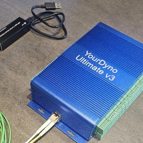
| YourDyno Standard v5 / Ultimate | Instrument boxes and PC software for inertia, chassis, engine and hub installations. Standard v5 provides speed and load-cell inputs and brake-control outputs; the supplier offers kits for eddy-current and water-brake systems. Chassis kit; Standard instructions. | Specify brake power supply or water-valve actuator and sensors. The Standard instructions describe two boxes in tandem or an Ultimate for a four-hub installation; confirm exact channels and options. |
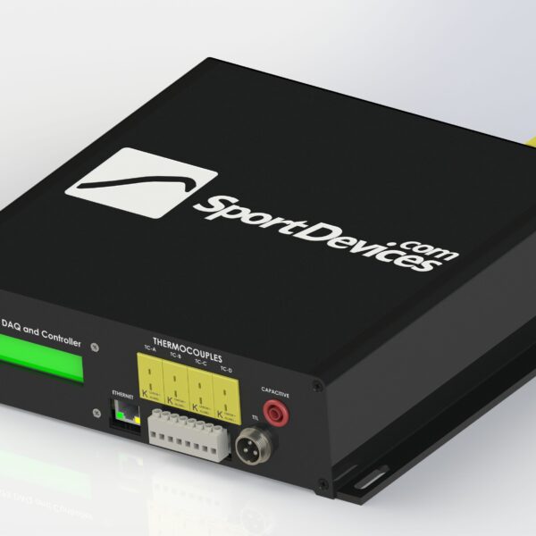
| SportDevices SP1+, SP5 and SP6 | DAQ and brake-control families used with SportDyno software. The SP5 describes engine and chassis testing and optional AWD; the SP6 offers two-brake and four-hub configurations. | SP1 and SP1+ differ; SP5 AWD requires additional components and activation, and SP6 variants have different channel counts. Match the power supply, load cells and speed pickups to the installation. |
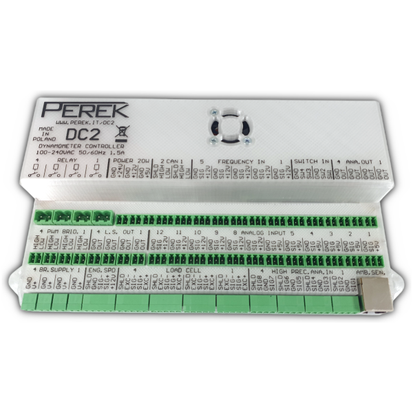
| PEREK DC2 / DC2L | Integrated controller/computer and Dyno2 software for inertial and braked installations. PEREK describes DC2 and DC2L variants and supports upgrades of existing hardware. | DC2 supports independently controlled 4WD chassis and four-hub layouts; DC2L has a more limited configuration range including mechanically synchronised 4WD chassis. A compatible eddy-current power module or valve actuator is separate from the control signal. |
| Dynostar DAS A801 | Roller-chassis upgrade kit with Dyno Station software, data-acquisition and junction boxes, remote, drum-speed sensor and load cell. The published kit also lists an eddy-current brake power supply and calibration weight. | Confirm brake voltage/current, axle arrangement and whether the supplied power stage and sensor interfaces suit the old dyno. The listing describes roller-chassis retrofits, not every dyno layout. |
| Accudyno Forza DS | Acquisition and digital brake control for absorber dynos, including hydraulic and eddy-current applications; the supplier describes automatic control through voltage, PWM or servo outputs. Accudyno overview. | The eddy-current brake power supply is not included in the cited product. Check the available speed/load channels and the separate hub-specific option for the intended arrangement. |
| Performance Trends Dyno DataMite | DataMite hardware and software for engine or chassis inertia and absorber measurements. The supplier describes retrofits to several dyno brands; its controller guide describes an eddy-current control setup. | DAQ size, software edition, controller and brake power box are distinct choices. Confirm whether the quotation includes automatic load control and the appropriate power stage or water-valve drive. |
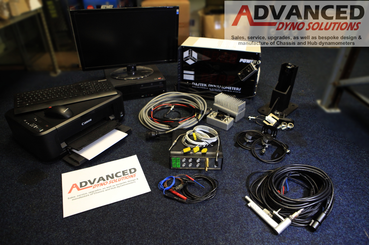
| Dastek upgrades through Advanced Dyno Solutions | ADS lists Dastek controller upgrade packages for existing 2WD and 4WD dynos, plus SportDevices accessories. See the Dastek profile. | Request the package's supported dyno, channels, brake driver, software and installation details. The listing alone does not establish every feature or compatibility with every make. |
| SuperFlow WinDyn5 conversions | Configurable control and acquisition conversions for engine and chassis test cells. SuperFlow's brochure names its own machines and several third-party makes, including Froude, Stuska, Maha, Dynojet and Dynocom. | This is a configured test-cell conversion; confirm the exact model, brake, valve arrangement, sensors and integration with SuperFlow. A listed make is not a guarantee for every machine. |
| 6DM REO-dEC R2 / REO-dCA R2 | The dEC R2 is an engine-dyno controller; dCA R2 expands it into a test-bed control and acquisition system. The supplier offers output modules for hydraulic, eddy-current and AC applications. | Intended for engineered engine-test installations and upgrades. Specify the actual absorber, throttle, transducer box and interfacing; confirm any particular chassis-dyno application separately. |
| Hydra-Test HTC-S | Modular acquisition and control system which the supplier says can be adapted to transmission stands, engine and chassis dynos; it lists configurable inputs, outputs and closed-loop modes. | Discuss the application with the supplier. Channel capacity, wiring, control strategy and brake interface depend on the engineered configuration; do not assume a universal drop-in kit. |
| dynoKRAFT ADAQ | ADAQ software and ADAQbase hardware are described with manual, semi-automatic and PID or non-PID brake modes; the supplier describes four-hub support using two base controllers. | Offered with dynoKRAFT equipment; ask the supplier whether an existing third-party machine can be converted and which hardware and brake power electronics are required. |
Measurement-only, older and other options
- SportDevices SP3 is a useful older retrofit example: its published instructions explicitly say it measures a braked dyno but does not control the brake. An existing brake controller is required.
- DTec DYNertia3 supports inertia measurement and open-loop brake measurement. Its manual states that it does not automatically vary brake load to hold a selected RPM. A separately controlled absorber remains necessary.
- Accudyno Gyra DS is the maker's inertia-measurement system; Forza DS is the separate absorber-dyno system. Do not assume a Gyra inertia kit supplies load control.
- Precision DynoTech describes DAQ products and RevBench software for digitising older dynos. Confirm automatic brake-control hardware and supported operating modes with the supplier.
- SAJ DCATS and Dyna Pro brake upgrades are examples tied to the supplier's own dyno families. Dyna Pro describes adding an actual eddy-current brake to specified inertia dynos, not simply changing software.
- DIY-Dyno is an open-source ESP32 measurement and control project for builders. Its repository describes an alpha-stage project; check the current implementation and validation before relying on any brake-actuation or safety function.
What to specify before replacing a controller
Identify the mechanical dyno and absorber separately from its existing electronics. Record the roller or hub count, axle linkage, absorber torque and speed envelope, field voltage and current or hydraulic-valve type, load-cell range and wiring, speed-pickup signals, engine-RPM source and power supply. Confirm whether the intended job needs inertia-only runs, steady-state hold, controlled sweeps, independent axle control, logging, CAN or a particular correction method.
Ask the supplier which power electronics or actuators, sensors, licences, wiring, calibration tools, emergency-stop interface, software, installation and support are included. Set up and verify roller inertia, speed and load-cell calibration and the response of the entire control and safety chain using the equipment maker's procedures. Replacing the electronics does not increase the brake's mechanical or cooling rating and does not give an absorption-only brake motoring capability.
Sources
- University of Edinburgh: dynamometer control research, historical review.
- Active control of an engine dynamometer, feedback and PI/PID comparison.
- Closed-loop torque and speed control on an eddy-current dynamometer, throttle and absorber control example.
Controller hardware, power stages and measurement
A complete dyno control installation is a chain of components. The measurement interface reads speed pickups and torque sensors; the real-time control unit calculates the load demand; a power stage supplies brake-coil current or drives a hydraulic actuator; and the operator software configures runs, graphs and reports. Some products put several of these functions in one box. A handheld pendant is an operator interface and does not necessarily replace the data-acquisition unit or brake driver.
- Speed: roller, hub or absorber RPM and engine RPM are different channels. Pickups may be Hall-effect, optical, variable-reluctance or derived from the ECU. The input circuit, tooth count, polarity, signal levels, maximum frequency and gearing must match the particular pickup. An engine RPM channel is not a substitute for a roller or hub speed measurement.
- Torque: strain-gauge load cells need an appropriate excitation supply, bridge input, amplifier, mechanical lever arm and calibration. Other systems use a shaft transducer or a calibrated hydraulic pressure model. Check the sensor range and its installation; the physical brake reaction and power absorbed during an accelerating run are not necessarily the whole shaft torque.
- Brake drive: PWM, a 0–5 V or 0–10 V command, a motor/servo position signal or a digital message is normally a control signal, not a universal high-current coil supply. An eddy brake needs a properly rated field power unit; a water or oil brake may need a compatible valve, motor, feedback sensor and actuator electronics. An AC regenerative dyno needs its own correctly specified inverter and electrical protection.
- Additional channels: analogue pressure and lambda, thermocouples, weather stations, CAN and OBD interfaces can improve diagnosis, but the number of sockets does not prove that every sensor, protocol or licence is included. Check voltage, isolation, bandwidth and supported message definitions.
For a four-hub or independent-axle dyno, count the actual speed channels, torque channels, brake commands, power stages and control loops; a four-wheel-drive display or a single combined torque reading does not by itself prove four independently controlled hubs. Depending on the vehicle, electronic speed matching and a mechanical axle link have different limitations. A controller cannot remove the absorber's torque–speed or cooling limits. See PEREK's application and peripheral guide.
Feedback, rates and test modes
The load controller may use a speed loop, a torque loop and, on some machines, a separate throttle or valve-position loop. As an example rather than a universal requirement, PEREK documents 1,000 Hz microcontroller loops and separate slower software functions. Dynolyze quotes a 1,200 Hz brake-current loop and PWM for its own power unit. These figures describe different parts of different systems; neither number alone proves the accuracy, response or safety of the complete dyno.
Speed hold adjusts brake demand to oppose the engine at a chosen speed; a controlled ramp moves that target through a range; fixed brake demand and a free inertia run are different tests. Torque hold needs a calibrated force or torque signal. A vehicle can accelerate against a brake without the controller actively enforcing a specified ramp, so check exactly what the product means by a “sweep”. Road-load and inertia simulation depend on the available software and actuators, while active motoring requires a suitable powered machine.
Examples of controllers supplied with dynamometers
These are manufacturer-specific examples, not claims that the named controller fits every generation or that the software alone drives a brake. For a deeper model-by-model guide see Original equipment dynamometer control systems.
| Dyno and factory controls | Hardware and software examples | What to check |
|---|---|---|
| Dynojet DynoWare RT / Power Core | DynoWare RT provides acquisition and expansion; Power Core includes WinPEP 8 Dyno Control and Data Center. The Vector-X4000 manual describes two eddy-brake drivers, two speed pickups and load-cell calibration. | The RT product description lists four 0–5 V inputs, ignition/optical RPM inputs, DJ-CAN and Ethernet; some sensors are optional. Brake, software and upgrade fit depend on the dyno. |
| Dynolyze hub controller | The maker lists 2/4 hub-speed, load-cell and brake-temperature inputs with independent brake PID loops; a remote can operate basic functions without a PC. The PC supplies analysis. Hardware and software details. | Check selected hub count, brake power units, optional CAN/knock inputs and software options for the actual package. |
| Dynapack hydraulic hub controls | Dynapack describes earlier axle-based control and newer hardware with separately controlled hubs; the manufacturer's independent-hub information discusses operating modes and existing pod compatibility. | Identify controller generation, pod configuration, supported independent channels and the exact upgrade path before ordering parts. |
| Mainline DynoLog CCS | CAN Control System combines controller hardware, distributed CAN modules and Windows software. Mainline's ProHub AWD CCS describes fixed-speed, load and programmed test modes. | Channel count, sensors, 2WD/AWD configuration and software options depend on the model and package; do not assume older systems use CCS. |
| Rotronics Hubscan / Dynascan | The Hubscan range describes Dynascan Essential and Advanced packages, depending on model. The brochure describes test and reporting functions. | Workshop eddy-current Hubscan and industrial Hubscan AC are different machines. Check software version, acquisition modules and options separately. |
| ROTOTEST Energy | Energy uses a real-time system control unit, drive/power cabinet and electric machines; DynoVision handles operation and Datmon measurement/reporting. The 4WD datasheet identifies an HDC controller and road-load modules. | Earlier VPA-RX machines are hydraulic. Four-quadrant motoring and recovery depend on the complete Energy drive configuration. |
| Dyno Dynamics / Dynotech | Dynotech Series II describes CAN-based control and data integration; upgrades are available for specified earlier systems. Series II information. | Identify original analogue, digital, A2W or later upgrade by serial number, hardware and licence. A replacement remote is not necessarily a replacement brake controller. |
| COSBER / DynoCosber | The supplier describes dyno software, a handheld control and PID load control as part of its own systems. Manufacturer catalogue. | Independent retrofit compatibility with other dyno makes has not been established. |
More detail on aftermarket and replacement systems
SportDevices: distinguish the SP generations
SportDevices supplies SportDyno software and several different hardware families. The SP1 V4 is an inertia acquisition kit; the historical SP3 measures a braked dyno but explicitly needs a separate brake controller. The older SP4 is a speed controller. Do not treat these names as interchangeable.
The SP5 lists two brake/roller-speed inputs, two load-cell inputs, six 0–5 V analogue channels and eight K-type thermocouples. Its AWD version requires the additional parts and firmware described by the supplier. SP6 adds four roller inputs, up to four load cells, eight analogue channels and two CAN buses; its HUB-4 configuration includes four speed sensors, four load cells and four brake power supplies according to the kit listing. Both describe inertia, steady, ramp and fixed-brake modes and some basic remote operation without the PC. Verify the exact variant, included kit and current software.
YourDyno Standard and Ultimate
YourDyno describes its Standard instrument box with two digital RPM inputs, two load-cell inputs, two brake-control outputs, three 0–5 V analogue inputs and one K-type thermocouple. Its instrumentation guide says a four-brake hub setup can use two Standard boxes and notes CAN activation is licensed. A brake output is a command to a suitable power supply or actuator, not the power stage itself.
The Ultimate v1/v2/v3 instructions describe four load-cell inputs, eight thermocouple inputs and six digital speed/frequency inputs; the analogue input count differs by generation. Confirm version, CAN licence, power supplies, sensors and software options with the supplier.
PEREK, DataMite and configured conversions
PEREK DC2 and DC2L integrate a computer with a real-time control and acquisition system. Its specification lists DC2 with four load-cell inputs and support for 4WD hub and unsynchronised chassis layouts; DC2L has one load-cell input and a more limited application range. The BD3.1 and compatible actuators are separate equipment; confirm the brake interface and exact package.
Performance Trends DataMite offers different sizes of data logger and software for inertia or absorber dynos. Separate controller options address brake actuation; do not assume every DAQ kit provides automatic load control. SuperFlow WinDyn conversions describe engineered control upgrades for air- and water-cooled eddy brakes, including multi-absorber chassis installations. Brake current, sensor interface and test-cell integration are specification-dependent.
Commissioning an upgrade
Before removing old electronics, document the existing sensor types and scaling, brake nameplate and field supply, roller or shaft geometry, wiring, controller settings, licenses and original calibration. Agree a channel-by-channel mapping, what hardware is retained, braking outputs, emergency-stop chain and fault responses with the installer. Archive original configuration and representative test data where accessible.
After installation, follow the suppliers' procedures for mechanical inspection, zero and traceable load-cell checks, speed and gear verification, roller inertia where applicable, actuator direction and controlled-response tests. Check sensor loss, communication faults and protective interlocks as specified for the actual equipment, and compare repeat runs under matched conditions. Record the as-built wiring, software/firmware versions and calibration. Do not assume a retained sensor is compatible solely because its connector fits.
Integrated manufacturer-specific controls
COSBER / DynoCosber describes its own software, handheld controller and PID load control as part of its chassis-dyno systems. The available sources do not establish a separately sold universal retrofit for other makes; confirm compatibility directly. COSBER dyno catalogue.
Related company profiles
SportDevices · YourDyno · PEREK · Dastek · Froude.