Removed text is struck through; added text is highlighted.
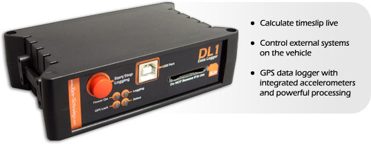
The DL1 CLUB and DL1 MK3 refer to the same standalone in-car logger. It records GPS, accelerometer and connected sensor data for analysis.
Image: Race Technology, reproduced with permission; manufacturer source.
Specifications and capabilities
The manufacturer specifies 5 Hz GPS, a three-axis accelerometer, SD/SDHC card storage and eight analogue inputs; additional inputs and interfaces depend on options. It has no integral dashboard screen. Manufacturer specifications and documentation.
Data analysis softwareThe manufacturer lists Analysis for viewing and examining DL1 CLUB/MK3 recordings; retrieve the recorded run using the unit’s documented storage or USB workflow. Manufacturer documentation.Race Technology Analysis example; the available channels and video depend on the recording and enabled options. Image: Race Technology, reproduced with permission; manufacturer source.Download Race Technology software for Windows. Check the current version and any licence or hardware requirements; some advanced functions require a unit-linked licence. See the Race Technology software overview for features and licensing.
Pinouts and cabling
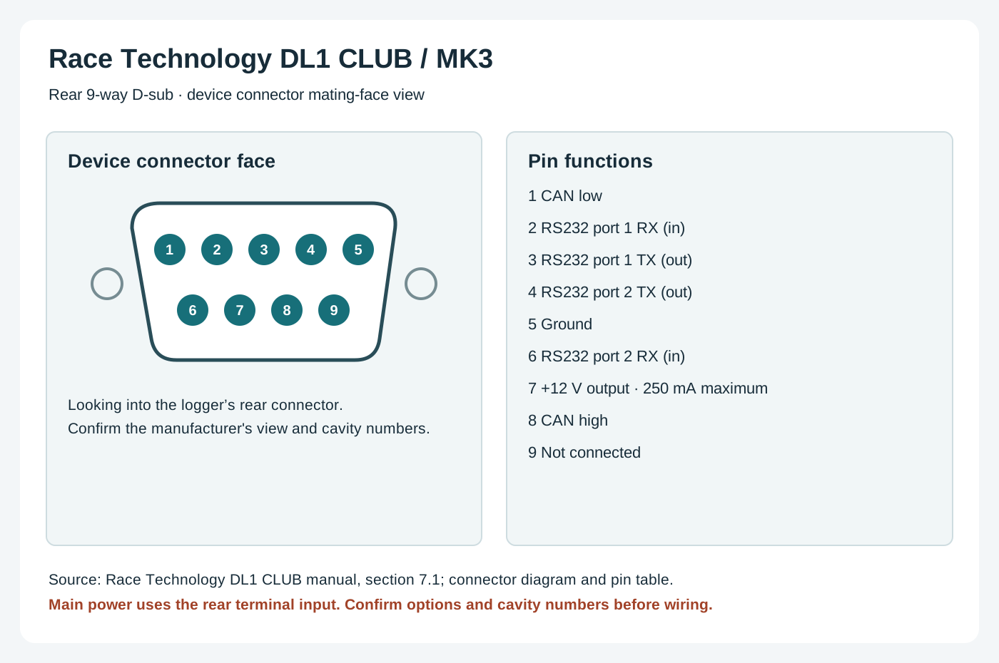
Data-port pinout; pin 7 is an accessory output, not the main power input. Check CAN and other options on the unit.
PinFunction1CAN low2RS232 port 1 RX (data in)3RS232 port 1 TX (data out)4RS232 port 2 TX (data out)5Ground6RS232 port 2 RX (data in)7+12 V output (250 mA limit)8CAN high9Not connected
Connector diagram; consult the linked manufacturer drawing to confirm the view and variant.
Manufacturer connection reference.
Check the connector number, version and options on the actual unit against the manufacturer's documentation before wiring. Disconnect power before changing connections.
Wiring overview
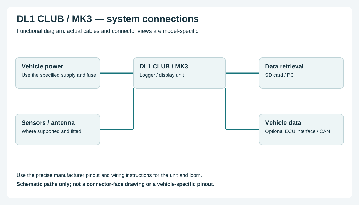
Functional wiring overview; consult the manufacturer for actual connector pins and harnesses.
Functional wiring: connect the vehicle supply to the designated main power terminals, antenna to the GPS input, sensors to their specified inputs and an optional compatible ECU interface to the configured data port. Consult the connector illustration and source for exact terminals.
Return to the Race Technology manufacturer page.
Rendered revisions
Open each version to inspect formatting, tables and photographs.
Revision 1: Race Technology DL1 CLUB (DL1 MK3)
The DL1 CLUB and DL1 MK3 refer to the same standalone in-car logger. It records GPS, accelerometer and connected sensor data for analysis.
The manufacturer specifies 5 Hz GPS, a three-axis accelerometer, SD/SDHC card storage and eight analogue inputs; additional inputs and interfaces depend on options. It has no integral dashboard screen. Manufacturer specifications and documentation.
Pinouts and cabling
Data-port pinout; pin 7 is an accessory output, not the main power input. Check CAN and other options on the unit.
Pin
Function
1
CAN low
2
RS232 port 1 RX (data in)
3
RS232 port 1 TX (data out)
4
RS232 port 2 TX (data out)
5
Ground
6
RS232 port 2 RX (data in)
7
+12 V output (250 mA limit)
8
CAN high
9
Not connected
Connector diagram; consult the linked manufacturer drawing to confirm the view and variant.
Check the connector number, version and options on the actual unit against the manufacturer's documentation before wiring. Disconnect power before changing connections.
Wiring overview
Functional wiring: connect the vehicle supply to the designated main power terminals, antenna to the GPS input, sensors to their specified inputs and an optional compatible ECU interface to the configured data port. Consult the connector illustration and source for exact terminals.
The manufacturer specifies 5 Hz GPS, a three-axis accelerometer, SD/SDHC card storage and eight analogue inputs; additional inputs and interfaces depend on options. It has no integral dashboard screen. Manufacturer specifications and documentation.
Data analysis software
The manufacturer lists Analysis for viewing and examining DL1 CLUB/MK3 recordings; retrieve the recorded run using the unit’s documented storage or USB workflow. Manufacturer documentation.
Race Technology Analysis example; the available channels and video depend on the recording and enabled options. Image: Race Technology, reproduced with permission; manufacturer source.
Check the connector number, version and options on the actual unit against the manufacturer's documentation before wiring. Disconnect power before changing connections.
Wiring overview
Functional wiring overview; consult the manufacturer for actual connector pins and harnesses.
Functional wiring: connect the vehicle supply to the designated main power terminals, antenna to the GPS input, sensors to their specified inputs and an optional compatible ECU interface to the configured data port. Consult the connector illustration and source for exact terminals.