Overview
RACELOGIC's VBOX Motorsport range uses satellite positioning for circuit driving, driver coaching and motorsport analysis. Different models add vehicle data, a driver display or synchronised video. Video VBOX products record the data used in the video overlay as well as footage for later comparison. Features vary by model and hardware generation; check the exact part number before specifying a system. [1]
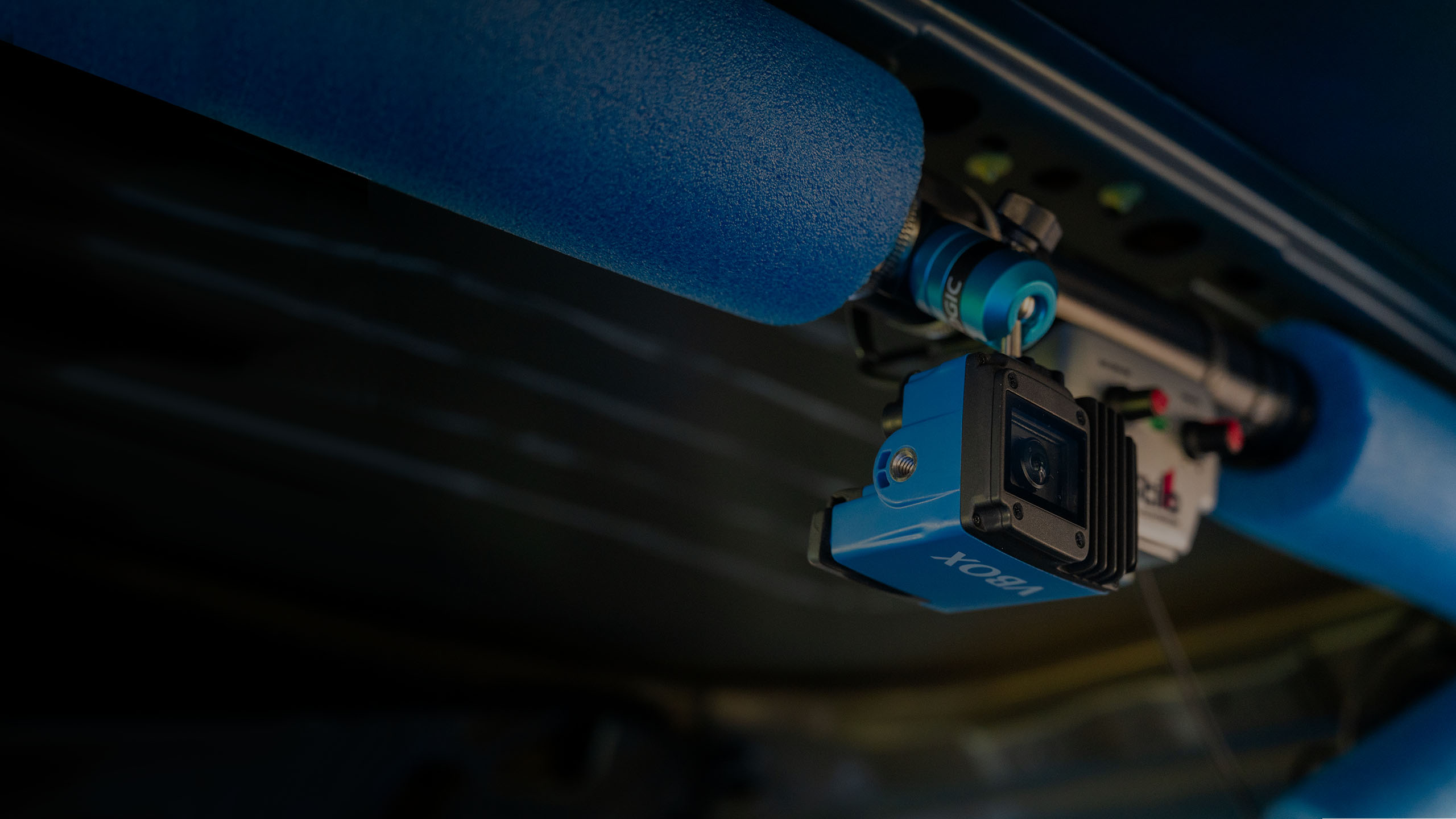
Manufacturer photographs: VBOX Video HD1 · VBOX Video HD2 and analysis software. Images: RACELOGIC / VBOX Motorsport; rights remain with the manufacturer.

Models
Individual model pages: VBOX Video HD1 · VBOX Video HD2 · LapTimer S · LapTimer R · Mini LapTimer.
VBOX LapTimer and Mini LapTimer
The VBOX LapTimer family combines a driver display with GNSS data logging to an SD card. It provides lap timing, position-based predictive delta time and speed comparison LEDs; data can be reviewed in Circuit Tools after the session. The manufacturer lists the Mini LapTimer at 10 Hz and current LapTimer S and R versions at 25 Hz, with side and rear connectors respectively. Hardware generations differ: check the part number and manual. The LapTimer is not itself a Video HD1 or HD2 camera system. The product page also contains RACELOGIC photographs. LapTimer S datasheet.
VBOX Video HD1

HD1 integrates a single video camera, GNSS antenna and recorder in a compact vehicle-powered unit. It records 1920 × 1080 video at 30 frames per second and 25 Hz multi-constellation GNSS data, with an overlay including lap times, position, speed and g-force. It has two isolated CAN interfaces supporting CAN 2.0 and CAN FD, and can log up to 80 CAN channels. Speed-triggered recording, an HDMI output and optional predictive lap timing display are available. Circuit Tools 3 is included. [2] [1]
VBOX Video HD2 / HDMI
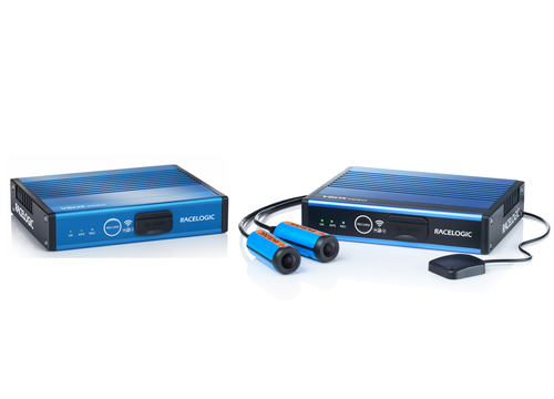
HD2 accepts two camera inputs and synchronises 1080p30 video with position and vehicle data; the current 25 Hz version supports a customisable overlay and up to 80 CAN channels. The optional OLED display provides predictive lap timing. HDMI is provided on the HDMI variant. Older versions of HD2 used 10 Hz GNSS; identify the hardware version and consult the appropriate manual and datasheet rather than assuming all units have 25 Hz or HDMI. [3] [4] [5]
Live video with HD2 HDMI
The HD2 HDMI variant can output real-time video and audio to an HDMI-compatible monitor, recorder or separate streaming device. RACELOGIC describes using a LiveU Solo HDMI encoder to transmit HD2 video to remote viewers, including back to the pits. This requires the HDMI-equipped HD2, suitable cable, separate encoder, network connectivity and relevant service arrangements. HDMI output alone is not an internet connection or a remote numeric telemetry feed. Coverage, network capacity and delay affect a live stream; the locally recorded data and video can also be reviewed later. Check the HD2 product information for compatible firmware and setup software and confirm event rules before transmitting.
Analysis and setup
Circuit Tools allows comparison of laps, position on track, sector and delta times, and synchronised video. Use speed traces and available brake, throttle and gear channels to investigate where time was gained or lost. HD1 is configured using VBOX Video Setup and offers phone-based camera preview; HD2's setup software configures the logger, CAN channels and overlay layout. The capabilities of an analysis installation may vary by software version. [2] [6]
Vehicle data and installation considerations
- Position, speed and lap timing come from GNSS; engine speed, throttle, brake pressure and other vehicle parameters need an appropriate source and a correctly configured interface. A listed channel is not proof that a particular vehicle or ECU broadcasts it. [3]
- Confirm the vehicle's CAN protocol, supported channels, wiring, bitrate, and the logger's hardware version before purchase or connection. HD1 has CAN FD; HD2 capabilities and available accessories depend on version. [2] [4]
- RACELOGIC describes connecting HD2 to AiM dashboards and to MoTeC equipment, with model-specific wiring and setup. Read its integration guidance and check the channel configuration. [3]
- Mount and secure the equipment and antenna in accordance with manufacturer guidance and the event or series rules. Confirm recording, satellite reception and channel scaling with a stationary and low-speed check before relying on a session.
Connectors, pinouts and cabling

Identify the exact model and hardware generation before wiring. The pin numbers below follow the manufacturer’s numbered connector diagrams; consult the linked drawings for the connector face and orientation, and distinguish the device socket from the mating cable’s wire side. RS232 TX and RX are labelled from the device documentation; check the other device’s direction. Disconnect power while checking continuity and individually insulate unused leads.
VBOX Video HD1 — Hirose power and communications
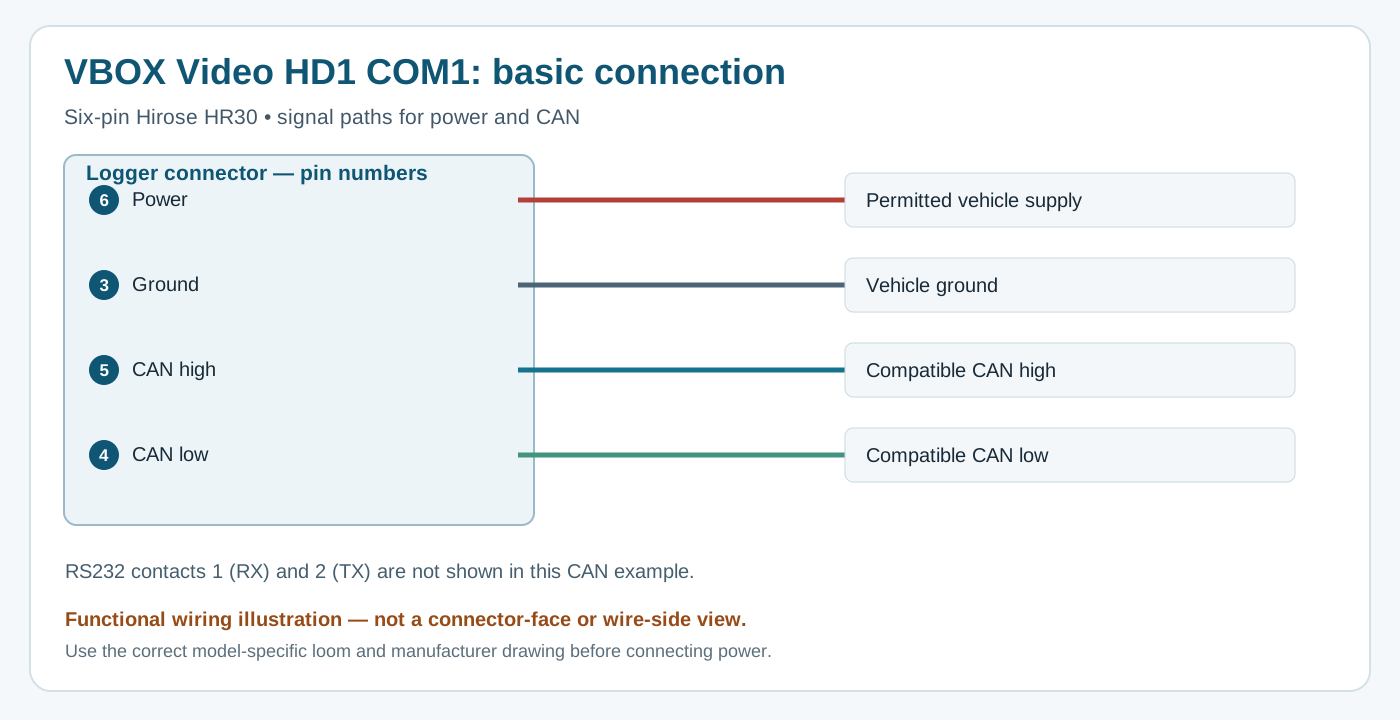
RACELOGIC’s HD1 pinout lists the same six pin assignments for both power/communications HR30 connectors, with the OLED display supported only on COM1. The separate hardware overview identifies COM1 with CAN 1 and the second power/communications connector with CAN 2, while the pinout page describes both as CAN 1. Confirm the individual bus selection and hardware with RACELOGIC before wiring; the shared pin labels alone do not resolve that documentation conflict.
| Pin | HD1 six-pin Hirose HR30 function |
|---|---|
| 1 | RS232 RX |
| 2 | RS232 TX |
| 3 | Ground |
| 4 | CAN low |
| 5 | CAN high |
| 6 | Power |
The same pinout lists the separate three-pin external microphone connector: 1 audio in, 2 mic bias, 3 audio ground. The hardware overview specifies 6–18 V DC supply and separate GNSS antenna and micro-HDMI connections; HDMI output needs an external recorder or streaming encoder for remote video.
For the manufacturer's HD1 installation harness, red is nominal +12 V, blue ground, yellow CAN high and green CAN low. Those colours apply to that harness only; verify the cable supplied. The manufacturer recommends ignition-switched power and cautions against connection to a jump-start lead or charger under load.
VBOX Video HD2 — power and CAN/serial
The HD2 pinout and rear-panel drawing shows separate LEMO connectors. Its two-pin POWER connector has pin 1 power positive and pin 2 ground; chassis is ground. The five-pin CAN/SER connector is a different socket from the five-pin USB connector.
| Pin | HD2 five-pin CAN/SER function |
|---|---|
| 1 | RS232 TX |
| 2 | RS232 RX |
| 3 | CAN high |
| 4 | CAN low |
| 5 | +V power output |
For completeness, the separate five-pin HD2 USB connector is documented as 1 USB ID, 2 DP, 3 ground, 4 USB 5 V and 5 DM. The two nine-pin camera connectors and four-pin microphone are also shown in the manufacturer’s pinout. Do not assume any HD1, HD Lite or vehicle connector has the HD2 assignment.
RACELOGIC’s HD2 CAN connection guide identifies RLCAB069L for OBD-II, RLCAB015L for bare-wire CAN and RLACS182L for clipping onto a CAN pair; check compatibility with the hardware generation and display arrangement. A physical OBD-II connection does not prove that the desired ECU channels are available: configure the correct CAN bitrate and channel decoding for the vehicle.