A rolling road, or roller chassis dynamometer, tests a complete vehicle with its driven tyres turning rollers while the vehicle is restrained. The measurement boundary is at the roller and tyre contact: gearbox, differential, bearings and tyres lie between the engine and the measuring system. It is useful for before-and-after tuning, fault finding under load, emissions and drive-cycle testing.
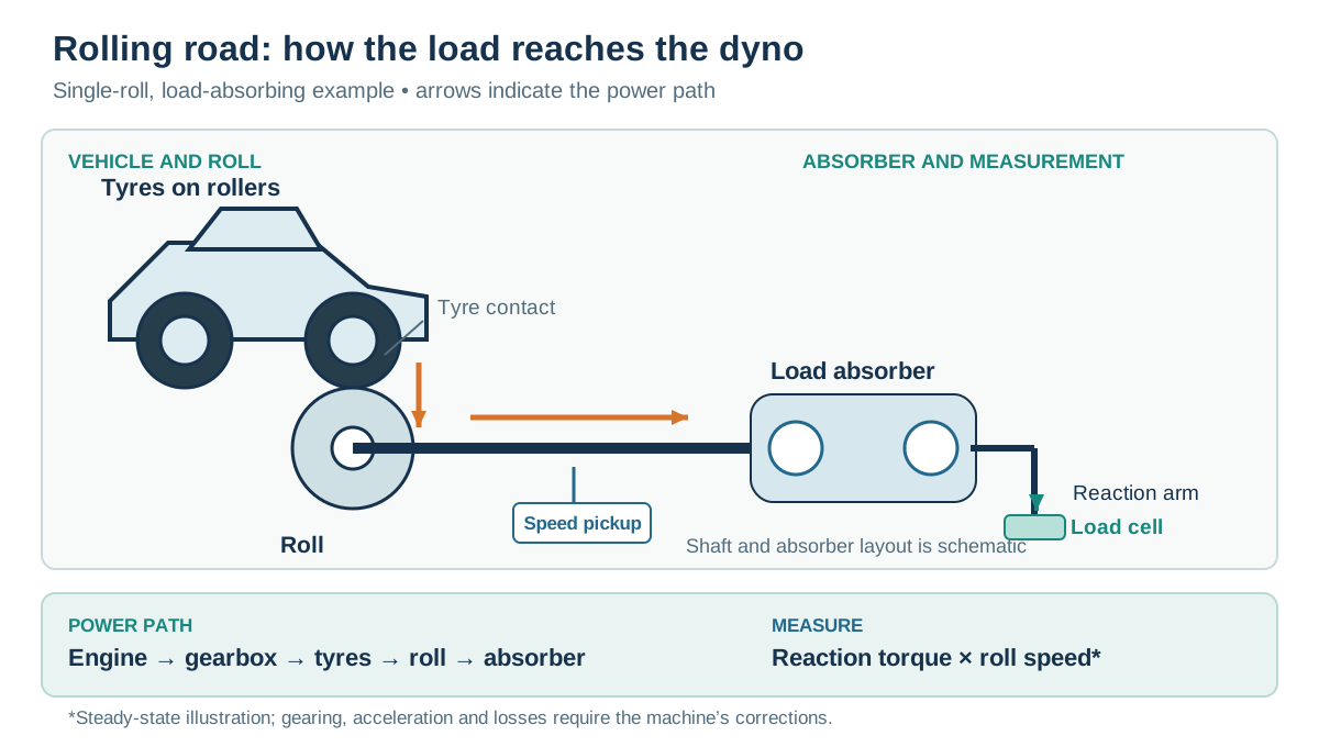
How a roller system works
The tyre turns a single large roller or a pair of smaller rollers. The rolls have known rotational inertia and may be connected to one or more power absorbing units. In a load-bearing design the rotating roll drives the absorber, while its housing is mounted so its reaction acts through a torque arm onto a load cell. A speed sensor measures roller rotation. At a steady point, power transferred through that measurement boundary is torque multiplied by angular speed; during acceleration, power also goes into accelerating the rolls and other rotating parts. The controller must account for the relevant inertia and losses. Mustang MD-600 operation manual.
Pure inertia machines calculate output from the acceleration of a calibrated mass. A braked machine can also impose controlled resistance: for example an eddy-current absorber turns vehicle power into heat and its excitation regulates load. A motor-capable electric machine can additionally drive the rollers where its design allows. These are capabilities of specific machines, not properties of every rolling road.
Testing and road simulation
In a sweep, the vehicle accelerates the rolls over an RPM range. A load-holding dyno can instead maintain a chosen speed while throttle or load is varied, useful for steady-state mapping and diagnosis. Road-load simulation can approximate rolling resistance, aerodynamic drag and gradient as functions of speed, with mechanical or electronically simulated inertia where fitted. Simulation depends on the chosen vehicle data, calibration and the control system's response; stationary testing does not reproduce every road airflow or transient. SAE 930392: chassis dynamometer performance tests.
Two-wheel and all-wheel drive
The equipment must suit driven axles, wheelbase, track, axle weight, speed and torque. Some all-wheel-drive vehicles require synchronised front and rear rolls or special procedures; permanent, automatically coupled and electrically driven axles can behave differently. Follow the vehicle and dyno maker's instructions; do not assume that a 4WD mode or disconnected axle is permissible.
Setup and interpreting a printout
Inspect tyre condition and pressure, secure the vehicle using approved restraint points, align it on the rollers, provide cooling airflow and exhaust extraction, and verify emergency stop and speed limits. Control tyre pressure, tie-down method, gear, warm-up and temperatures across comparisons. Tyre deformation, rolling resistance and slip, dyno and bearing losses, and roller geometry influence output and repeatability; twin-roller losses have been studied explicitly in SAE 2017-36-0212.
Report whether power is measured at the wheels/rollers or estimated at the engine, along with correction standard, gear, RPM source and conditions. A coastdown-based drivetrain-loss estimate is model-dependent; adding it to wheel power does not make a direct crankshaft measurement. Compare runs on the same calibrated equipment with consistent settings rather than treating different dyno figures as interchangeable.
Manufacturer example
Advanced Dyno Solutions describes a 500 mm single-roll eddy-current chassis system in 2WD and 4WD configurations, including a synchronised-roll option for compatible vehicles. Configuration and capacity depend on the system supplied; consult the manufacturer’s chassis-dyno page.
See also: Dynamometers overview · Rolling roads · Engine dynamometers · Hub dynamometers · On-car and portable systems · Inertia dynamometers.
Related company profiles
COSBER / DynoCosber manufactures roller dynos with integrated controls.
Advanced Dyno Solutions · Dyno Developments · Dyno Dynamics · Dynojet · Mustang Dynamometer · Dyna Pro.