Tuning Wiki

This is a historical revision. Read the current page or return to its history.

Page organisation in this revision
Page type
Technical article
Subject
Carburettors
Parent
Section level
Applies to
No ECU-specific applicability
Tool groups
None
Manufacturers
None

Changes from revision 1 to revision 11

Removed text is struck through; added text is highlighted.

Carburettors (often called carbs) can be classified in four independent ways: how they meter fuel relative to airflow, which direction air enters the throttle bore, how many barrels and stages they use, and whether they run naturally aspirated or under boost. Identifying the architecture first prevents misapplying jetting rules from one design to another.
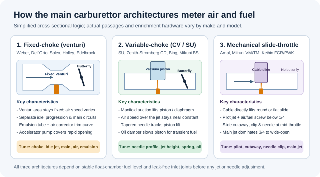
The three most widespread mechanical carburettor architectures: fixed-choke venturi, variable-choke (constant-depression/CV), and direct mechanical slide-throttle. Original diagram prepared for Tuning Wiki, CC BY 4.0.1. By metering principle (main & specialist architectures)ArchitectureHow airflow & fuel are matchedTypical makes & familiesKey tuning parts Fixed-choke (fixed venturi)A fixed venturi accelerates the air to create a pressure drop that draws fuel from jets. Separate circuits handle idle, progression, main flow, power enrichment and acceleration.Weber (DCOE, IDF, IDA, DGV), Dell'Orto (DHLA, DRLA), Solex, Holley (4150, 4160, 2300), Rochester Quadrajet, Carter/Edelbrock AFB & AVS2Venturi/choke diameter, idle/slow jet, main jet, air corrector, emulsion tube, power valve or metering rods, pump shooter/cam Variable-choke (constant depression / CV)Manifold suction downstream of a butterfly lifts a vacuum piston (SU) or rubber diaphragm slide (Stromberg, motorcycle CV) to keep air speed over the single main jet roughly constant.SU (H, HD, HS, HIF), Zenith-Stromberg CD, Bing Type 64/94, Mikuni BS/BST, Keihin CV/CVKTapered metering needle, jet height/seat, piston return spring, damper oil viscosity, idle mixture Sliding-valve variable venturi (VV)Movable venturi valves above conventional twin butterfly throttles slide horizontally with airflow and vacuum while pulling attached tapered metering rods; uses a cranking enrichment circuit rather than a choke flap.Ford / Motorcraft 2700 & 7200 VV (1977–1980s Ford/Lincoln/Mercury)Tapered metering rods, venturi-valve diaphragms, cranking enrichment solenoid, idle mixture & feedback controls Mechanical slide-throttle (jet & needle)A cable pulls a round or flat slide directly in the bore without a separate butterfly. Slide height sets venturi area while a tapered needle in a needle jet meters mid-range fuel.Amal Monobloc & Concentric, Mikuni VM & TM/HSR, Keihin PWK & FCR, Dell'Orto PHBH/VHSBPilot jet, air/fuel screw, slide cutaway, needle taper & clip position, needle jet/atomiser, main jet Flat-slide metering-rod (jetless)Replaces pilot, intermediate and main jets with a single precision-ground tapered metering rod (flat engine side, round intake side) riding in the fuel pickup bore; air-density differential compensates across altitude.Lectron (metering rod + power jet / PRO 3-circuit), SmartCarb SC2 (internally vented sealed bowl, external clicker)Metering rod profile & height, idle set screw, optional power jet (Lectron) Swinging-arm / hollow-spindle (jetless)Uses neither a venturi choke tube nor removable brass jets: a swinging arm on the hollow throttle spindle tracks a tapered groove in the float bowl and sprays fuel out of cross-holes in the spindle itself.Fish, Minnow Fish, Reece Fish (historic aftermarket & Imp/Mini/stock-car racing)Tapered main adjustment screw into throttle spindle, butterfly angle on spindle, swinging-arm groove Electronic / feedback carburettorRetains venturi metering with a solenoid-controlled air bleed or metering rod driven by an early ECU and narrowband oxygen sensor to hold lambda near 1 for a three-way catalyst.Pierburg 2EE Ecotronic, Rochester E4ME / E4MC, Motorcraft/Weber feedback unitsMixture-control solenoid dwell, TPS/vacuum switches, coolant sensors, base mechanical float & idle stops Diaphragm pumper carburettorUses crankcase or intake pressure pulses acting on a flexible pumping diaphragm and metering diaphragm instead of a gravity float bowl, allowing operation inverted or at any tilt angle.Walbro, Tillotson, Zama (chainsaws, karts, handheld and marine two-strokes)Low-speed (L) and high-speed (H) needle screws, metering lever height, pop-off pressure, diaphragm condition Floatless pressure / injection carburettorEliminates the gravity float bowl; fuel is held under pump pressure by servo diaphragm/poppet regulators and sprayed downstream of the throttle or at the supercharger eye while the venturi measures airflow only—immune to negative-G starvation.Bendix-Stromberg PS / PD / PT / PR (WWII & radial/inline aircraft engines, e.g. Allison V-1710)Air-metering venturi, pressure-regulator diaphragms, automatic mixture-control bellows, economiser valve Gaseous / LPG & CNG air-valve mixerA vacuum-lifted air-valve diaphragm meters vaporised propane (LPG) or compressed natural gas proportionally to airflow with no liquid float bowl or brass fuel jets.IMPCO (CA125, CA300, CA425), Bendix-Zenith gaseous mixersAir-gas valve profile/spring, power mixture screw, idle air/fuel adjustment, converter/vaporiser outlet pressureThe three main mechanical carburettor architectures: fixed-choke venturi, variable-choke (constant-depression/CV), and direct mechanical slide-throttle. Original diagram prepared for Tuning Wiki, CC BY 4.0.1. By metering principleArchitectureHow airflow & fuel are matchedTypical makes & familiesKey tuning parts Fixed-choke (fixed venturi)A fixed venturi accelerates the air to create a pressure drop that draws fuel from jets. Separate circuits handle idle, progression, main flow, power enrichment and acceleration.Weber (DCOE, IDF, IDA, DGV), Dell'Orto (DHLA, DRLA), Solex, Holley (4150, 4160, 2300), Rochester Quadrajet, Carter/Edelbrock AFB & AVS2Venturi/choke diameter, idle/slow jet, main jet, air corrector, emulsion tube, power valve or metering rods, pump shooter/cam Variable-choke (constant depression / CV)Manifold suction downstream of a butterfly lifts a vacuum piston (SU) or rubber diaphragm slide (Stromberg, motorcycle CV) to keep air speed over the single main jet roughly constant.SU (H, HD, HS, HIF), Zenith-Stromberg CD, Bing Type 64/94, Mikuni BS/BST, Keihin CVKTapered metering needle, jet height/seat, piston return spring, damper oil viscosity, idle mixture Mechanical slide-throttleA cable pulls a round or flat slide directly in the bore without a separate butterfly. Slide height sets venturi area while a tapered needle in a needle jet meters mid-range fuel.Amal Monobloc & Concentric, Mikuni VM & TM/HSR, Keihin PWK & FCR, Dell'Orto PHBH/VHSBPilot jet, air/fuel screw, slide cutaway, needle taper & clip position, needle jet/atomiser, main jet Electronic / feedback carburettorRetains venturi metering with a solenoid-controlled bleed or metering rod driven by an early ECU and narrowband oxygen sensor to hold lambda near 1 for a three-way catalyst.Pierburg 2EE Ecotronic, Rochester E4ME / E4MC, early Ford/Weber feedback unitsMixture-control solenoid dwell, TPS/vacuum switches, coolant sensors, base mechanical float & idle stops Diaphragm pumper carburettorUses crankcase or intake pressure pulses acting on a flexible pumping diaphragm and metering diaphragm instead of a gravity float bowl, allowing operation at any tilt angle.Walbro, Tillotson, Zama (chainsaws, karts, handheld and marine two-strokes)Low-speed (L) and high-speed (H) needle screws, metering lever height, pop-off pressure, diaphragm condition

The 1958 SU workshop manual explains the constant-depression principle directly: keeping air velocity over the jet nearly constant lets the carburettor atomise fuel cleanly at small openings without strangling peak airflow, which is why SU designs omit a separate fixed-choke idle jet and accelerator pump (relying instead on a damped piston whose brief lag enriches rapid throttle openings). In contrast, fixed-choke designs such as the Weber DCOE require dedicated progression drillings, emulsion tubes and a mechanical pump because venturi depression collapses at low air speed.

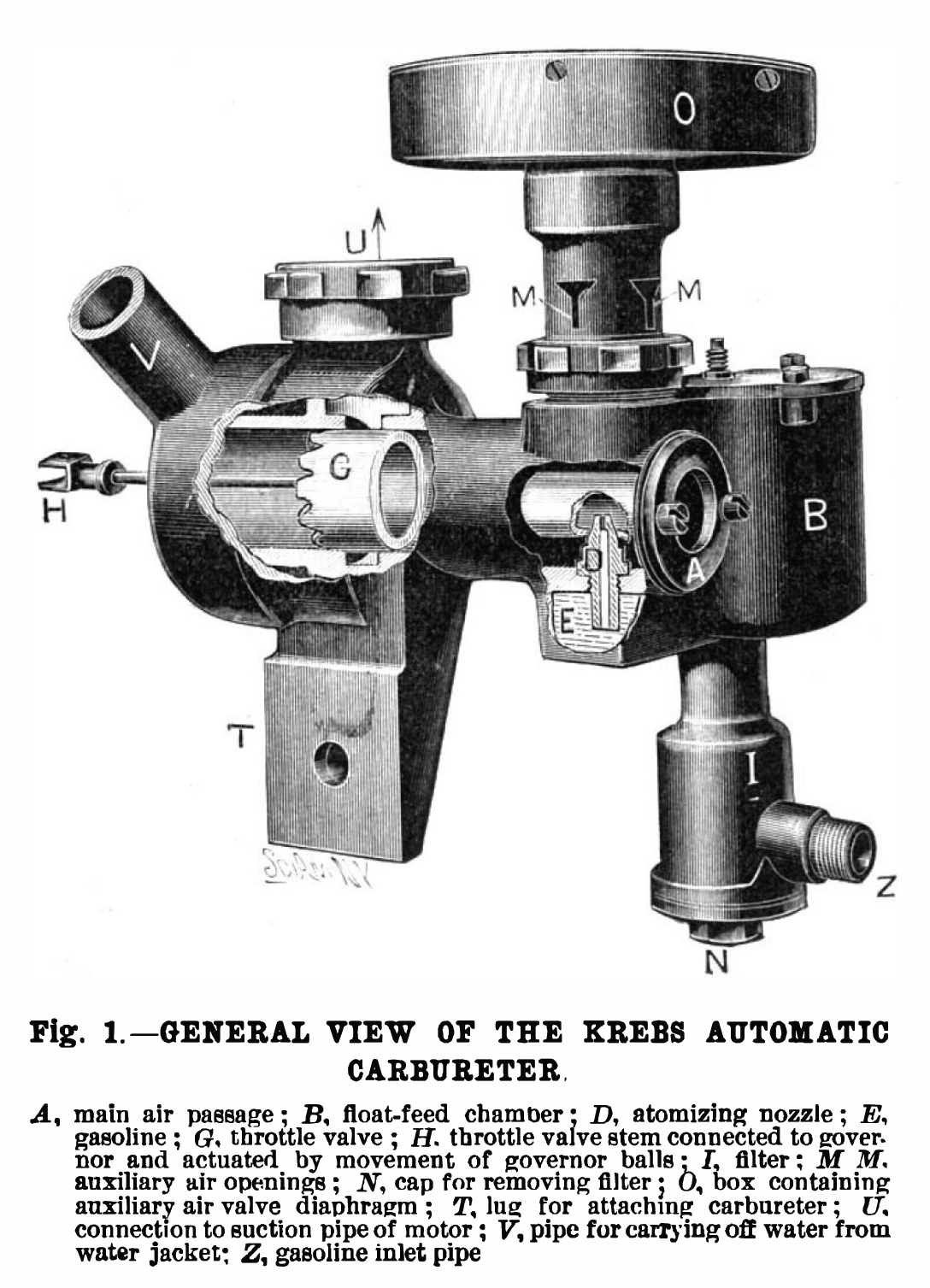
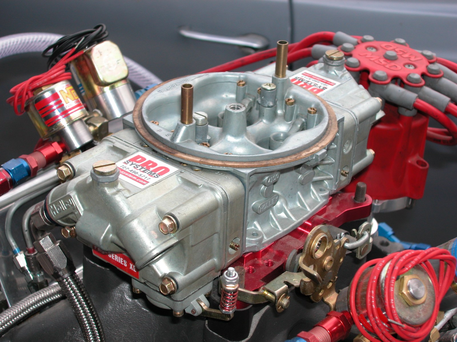
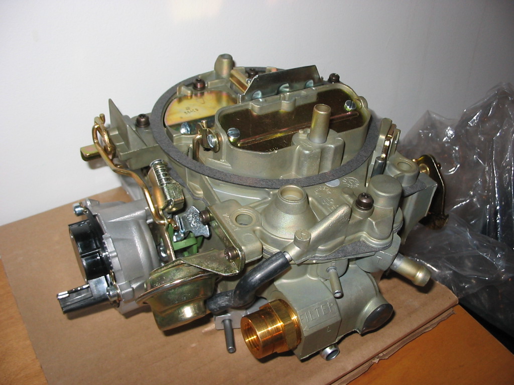
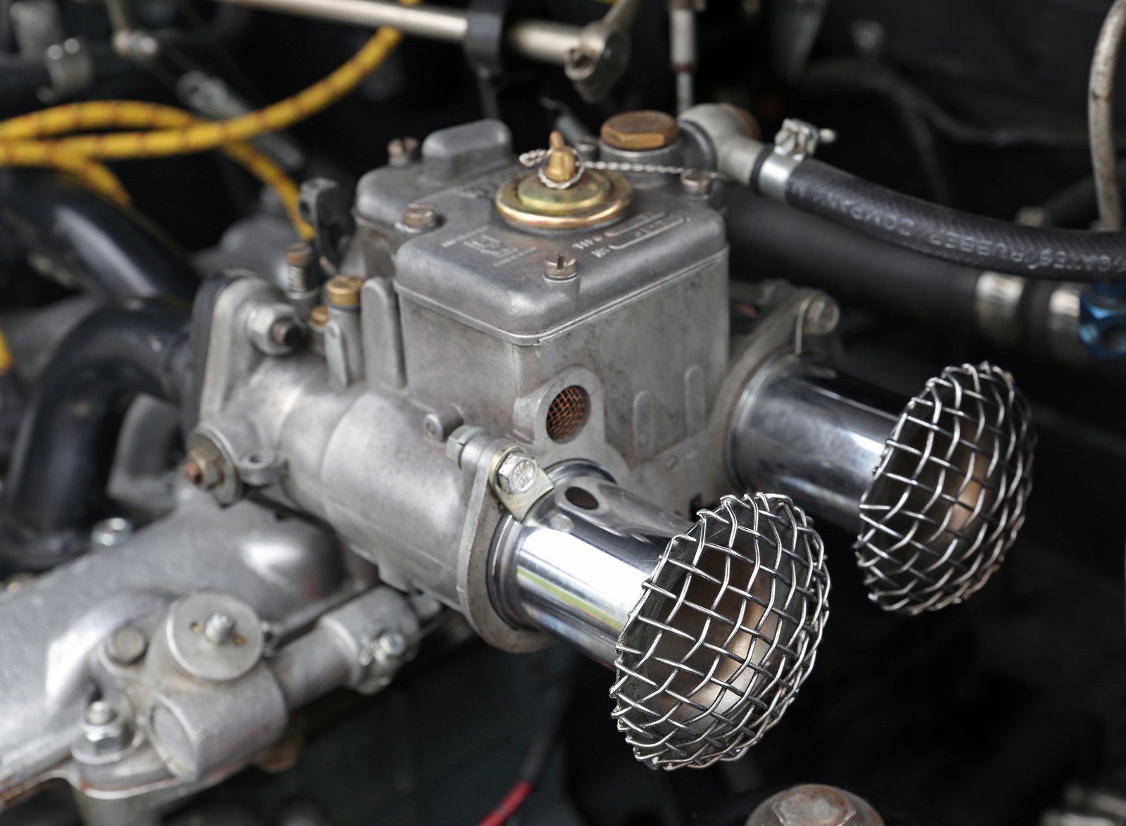
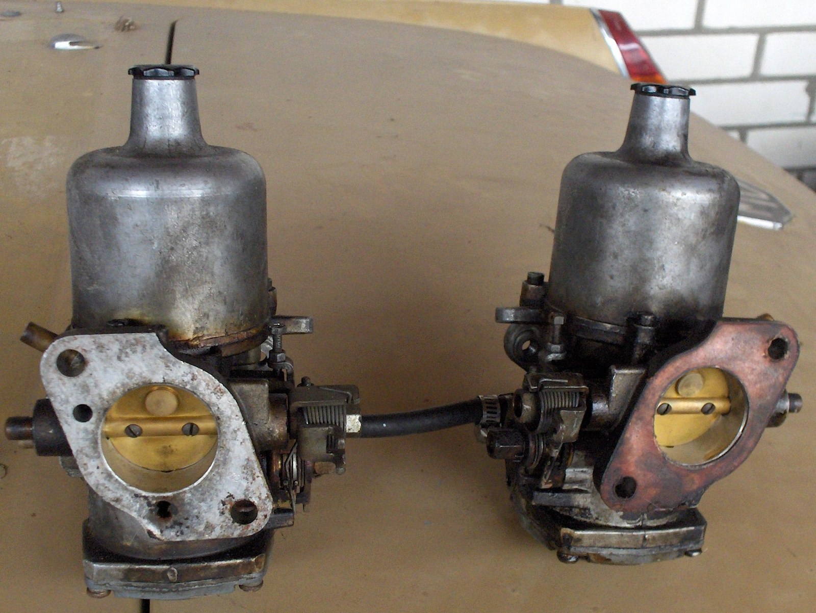
Fixed-choke sidedraft example: a Weber 40 DCOE on an Abarth 1000 Bialbero. Photo: Mr.choppers; resized. Wikimedia Commons, CC BY-SA 3.0.Variable-choke piston example: an SU constant-depression carburettor assembly. Photo: Sonett72, Wikimedia Commons, Public domain.Diaphragm constant-velocity (CV) motorcycle carburettor: Mikuni BS36SS from a Suzuki GN400. Photo: Wusel007, Wikimedia Commons, CC BY-SA 3.0.Mechanical round-slide example: a Mikuni round-slide carburettor. Photo: Beademung, Wikimedia Commons, CC BY-SA 3.0 DE.Mechanical flat-slide example: Keihin 39 mm flat-slide racing carburettors. Photo: andicati; watermark removed by A7N8X. Wikimedia Commons, CC BY 2.0.Floatless aircraft pressure carburettor: Bendix-Stromberg PB-12 B8 at the Finnish Air Force Museum. Photo: MKFI, Wikimedia Commons, Public domain.2. Earliest, veteran & vintage carburettor types (1826–1920s)Before modern venturi fixed-choke and piston constant-depression carburettors matured in the late 1920s and 1930s, pioneers tried several completely different ways to vaporise and meter liquid fuel:Early type / eraHow it workedInventors, makes & examples Vapour / evaporative mixer (1826–1880s)Early pre-automotive vapour apparatus heating or bubbling air through volatile turpentine or light spirits to produce a combustible gas mixture.Samuel Morey (1826); Luigi De Cristoforis (1876); Enrico Bernardi (1882 Motrice Pia) Rotary-brush atomiser (1870s)A pulley-driven revolving brush inside a fuel reservoir dipped into petrol and mechanically flung fine droplets into the intake air stream ahead of the piston suction.Siegfried Marcus (1872 patent / 1875 rotary-brush petrol vehicle) Surface / bubbling carburettor (1880s–1890s)Intake air passed over the surface of (or bubbled through) a warm brass reservoir of light petrol, picking up vapour by evaporation before entering a mixing slide valve. Sensitive to fuel quality, temperature and road vibration.Karl Benz (1885–1888 patent), early De Dion-Bouton, 1898 Fisson twin-cylinder Wick carburettor (1893–1900s)Replaced open surface slosh by drawing fuel upward via capillary action into rows of cotton wicks inside an upper vapour chamber; air drew across the saturated wicks and through wire-mesh gauze (an early fuel filter).Dr. Frederick W. Lanchester (1893–1896 Lanchester cars) Early spray-nozzle & float-feed atomiser (1884–1896)Introduced the float bowl with a needle shutoff valve feeding a spray jet inside a narrowed throat—laying the foundation for almost every float-bowl carburettor since.Edward Butler (1884–1887 "Inspirator" on Butler Petrol Cycle); Wilhelm Maybach & Gottlieb Daimler (1885–1896); János Csonka & Donát Bánki (1893) Longuemare & "iron-pot" / puddle carburettors (1900–1920s)Early brass/iron float-chamber spray and "puddle" units where fuel pooled in a small trough beneath the air passage or emerged through a slotted spray cone adjusted by a simple needle screw.French Longuemare (licensed by Holley Brothers in 1901), Holley 1904 "iron-pot", Ford Model T Holley three-screw puddle / Holley NH & Kingston L4 Spring-loaded auxiliary air-valve carburettor (1902–1920s)Used a spring-loaded flap or poppet valve to admit extra air as engine suction increased, counteracting the tendency of an uncompensated single jet to go overly rich at high RPM.George Schebler (1902 air-valve patent; Wheeler-Schebler, Marvel-Schebler), Arthur Krebs / Panhard & Levassor (1902) Leather-bellows variable-choke (1902–1905)Early suction-controlled variable-choke precursor to the modern metal-piston SU: intake vacuum collapsed or lifted a supple leather bellows attached to a tapered metering needle.Early Panhard & Levassor bellows carbs (1902–1904); George Herbert Skinner's prototype SU design (1904–1905) Twin-lever separate air-and-throttle slide (1905–1928)Pre-Amal motorcycle carbs featuring two independent handlebar levers—one lifting the throttle slide and one lifting a separate air slide—requiring the rider to mix air and fuel manually on the move.Brown & Barlow (B&B), Amac, Binks (merged into Amal in the late 1920s) Compound-jet / compensating-jet (1907–1930s)Paired a venturi main jet (which grows richer with airflow) with a gravity-fed compensating jet (whose constant flow per second leans out as airflow rises) so the combined delivery stays balanced across RPM.Early 20th-century Zenith (François Baverey's compound-jet design)Early float-feed carburettor: 1902 Daimler unit. Photo: Wikimedia Commons, Public domain.1902 Krebs automatic auxiliary air-valve carburettor patent drawing (FR325241 / GB190222655 / US734421A). Credit: A. C. Krebs, Wikimedia Commons, Public domain.3. By airflow orientation2. By airflow orientation

Downdraft: air enters from above and flows vertically downwards into the manifold. Very common on road cars (Weber DGV/IDF, Solex PICT, Holley/Rochester four-barrels) because gravity assists atomised droplets into the plenum and bonnet clearance is easier on V-engines and upright inline engines. Sidedraft (horizontal): air flows horizontally through the carburettor straight into the cylinder-head port. Favoured for multi-carburettor individual-runner performance setups (Weber DCOE, Dell'Orto DHLA, twin SU HS/HIF) because it provides a straight, short inlet path with minimal bends, at the cost of requiring clean float-chamber mounting geometry and careful throttle-linkage synchronisation. Semi-downdraft: tilted slightly downwards (for example 20° to 40° on certain SU HS and HIF installations) to clear inner wings or bonnet lines while preserving the straighter flow of a sidedraft. Updraft: air enters from below and rises into the manifold. Historically common on pre-war cars, stationary engines and tractors where gravity-fed fuel tanks sat above the carburettor and excess liquid fuel drained safely away from the cylinders; rare on post-war performance cars.

4. By barrel count and secondary stagingSingle-barrel (1V): one venturi and throttle feeding either a shared manifold plenum (Solex 34 PICT, single SU) or a single cylinder (motorcycle slide/CV carbs). Synchronous twin-choke (2V): both throttles sit on a common shaft and open identically together (Weber DCOE, IDF, IDA; Dell'Orto DHLA, DRLA). In a typical four-cylinder dual-carburettor setup, four chokes feed four individual runners (one choke per cylinder) so each cylinder has its own intake pulse and metering circuit. Progressive two-barrel (2V): a smaller primary barrel handles idle, light load and part-throttle cruising with strong air speed, and a larger secondary barrel opens mechanically or by vacuum above roughly half to two-thirds primary throttle (Weber DGV/DGAV, Pierburg 2E2/2E3, Aisan/Hitachi OEM units). Three-barrel (3V): exists in two completely different forms: (1) Honda's stratified-charge Keihin CVCC 3-barrel (two main barrels feeding the main cylinder intake plus a small third auxiliary barrel feeding a rich mixture to the pre-chamber torch-ignition valve on 1970s–1980s Civic/Accord CVCC engines), and (2) the late-1960s Holley 3160 (950 and 1,050 CFM), which paired two primary barrels with one huge undivided oval vacuum-operated secondary butterfly across a standard 4-barrel flange (Hagerty Holley 3160 review). Four-barrel (4V) square-bore vs spread-bore: square-bore carbs (such as the Holley 4150/4160 and Edelbrock Performer/AVS2) use four similar-sized throttle bores; spread-bore carbs (such as the Rochester Quadrajet and Carter Thermoquad) pair small primary bores for crisp low-speed signal and economy with very large secondary bores for top-end flow. Multi-carburettor staged racks ("Tri-Power" / "Six Pack" / "Dual Quad"): factory and hot-rod manifolds pairing three two-barrels (such as 3×Holley 2300 on Chrysler 340/440 Six Pack or 3×Holley 1904/1908 inline-six kits, where the centre carb runs idle/cruise and outer carbs open progressively) or two four-barrels (Chrysler Street Hemi 2×Carter AFB). Vacuum vs mechanical secondaries: on four-barrels, vacuum secondaries sense primary venturi airflow through a diaphragm so the secondary throttles only open as far and as fast as the engine can actually ingest air—avoiding the bog caused by opening too much area too early on heavy vehicles or automatic transmissions. Mechanical ("double-pumper") secondaries open directly via linkage and include a second accelerator pump to cover the sudden pressure drop when all four bores open together. See Holley 4160 installation instructions and Holley secondary diaphragm spring tuning.Square-bore four-barrel example: a Holley four-barrel performance carburettor. Photo: Rich Niewiroski Jr., Wikimedia Commons, CC BY 2.5.Spread-bore four-barrel example: a Rochester Quadrajet M4ME showing small primary and large secondary bores. Photo: Craigblock, Wikimedia Commons, Public domain.5. Forced-induction layouts: draw-through vs blow-through3. By barrel count and secondary stagingSingle-barrel (1V): one venturi and throttle feeding either a shared manifold plenum (Solex 34 PICT, single SU) or a single cylinder (motorcycle slide/CV carbs). Synchronous twin-choke (2V): both throttles sit on a common shaft and open identically together (Weber DCOE, IDF, IDA; Dell'Orto DHLA, DRLA). In a typical four-cylinder dual-carburettor setup, four chokes feed four individual runners (one choke per cylinder) so each cylinder has its own intake pulse and metering circuit. Progressive two-barrel (2V): a smaller primary barrel handles idle, light load and part-throttle cruising with strong air speed, and a larger secondary barrel opens mechanically or by vacuum above roughly half to two-thirds primary throttle (Weber DGV/DGAV, Pierburg 2E2/2E3, Aisan/Hitachi OEM units). Four-barrel (4V) square-bore vs spread-bore: square-bore carbs (such as the Holley 4150/4160 and Edelbrock Performer/AVS2) use four similar-sized throttle bores; spread-bore carbs (such as the Rochester Quadrajet and Carter Thermoquad) pair small primary bores for crisp low-speed signal and economy with very large secondary bores for top-end flow. Vacuum vs mechanical secondaries: on four-barrels, vacuum secondaries sense primary venturi airflow through a diaphragm so the secondary throttles only open as far and as fast as the engine can actually ingest air—avoiding the bog caused by opening too much area too early on heavy vehicles or automatic transmissions. Mechanical ("double-pumper") secondaries open directly via linkage and include a second accelerator pump to cover the sudden pressure drop when all four bores open together. See Holley 4160 installation instructions and Holley secondary diaphragm spring tuning.4. Forced-induction layouts: draw-through vs blow-through

Combining a carburettor with a turbocharger or supercharger changes the pressure reference around the float chamber:

Draw-through: the carburettor sits upstream of the compressor, so the carburettor itself always sees atmospheric pressure at its inlet and vacuum below the throttle. Traditional Roots-type superchargers and early carburetted turbos used draw-through layouts, which must be paired with a turbocharger carbon-face compressor seal capable of withstanding high throttle-closed manifold vacuum without drawing oil into the intake, and cannot normally run an intercooler downstream of the compressor because wet fuel mixture would puddle in the core. Blow-through: the carburettor sits downstream of the compressor (and any intercooler), so boost pressure fills the carburettor throat. If the float bowl remained vented only to atmosphere, boost pressure would push fuel back down the jets and starve the engine immediately. A blow-through conversion therefore requires: (1) referencing the float-bowl vents and fuel-pressure regulator 1:1 to bonnet/hat boost pressure so differential fuel pressure stays constant; (2) solid or nitrophyl floats that will not collapse under boost pressure; (3) sealed throttle shafts and gaskets; and (4) a boost-referenced power valve or enrichment circuit, because normal manifold vacuum stays low or positive under boost (Holley/Weiand supercharger carburetion reference).

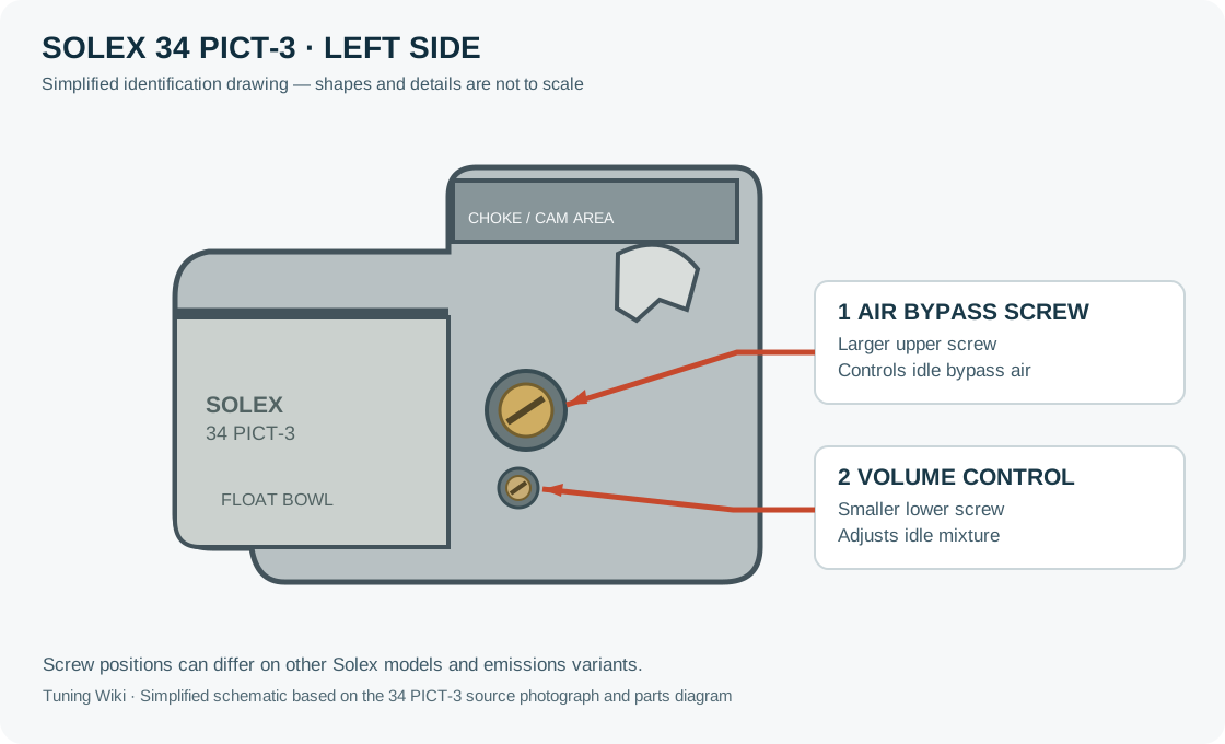
Adjustment diagrams for selected carburettor modelsThe linked illustrations identify controls on particular carburettors. Screw locations, functions and part numbers can change between models and diagrams; match the carburettor and use the key beside each drawing.Solex 30 PICT-3 and 34 PICT-3: EMPI's Solex service instruction sheet, exploded view and key, identifies the air-bypass screw as item 31 and the volume-control screw as item 35. The sheet covers other variants too; its idle-setting procedure distinguishes the PICT-3 from the PICT-2. Pierburg 2E3: the Pierburg 2E3 service manual has an opening exploded view identifying the fast-idle adjuster as 1 and the mixture adjuster as 3. In the separate idle-correction illustration on page 3 the throttle-plate screw is 1 and mixture screw is 4: these two drawings use different number keys. The manual says screws with tamper-proof caps or protective lacquer are not to be adjusted. Jikov 2928CE: CVKustoms’ 2928CE illustrated reference, figure 1 reproduced from the Jawa 350/640 manual, identifies the idle-adjust screw as 9 and the mixture-adjust screw as 10. The later adjustment illustration uses a different number key; other Jikov models may differ. Bing constant-depression carburettors on BMW R75/5–R100: Ulis Motorradladen’s parts catalogue, group 13c, identifies the mixture-regulating screw as item 6 and the butterfly-adjusting screw as item 9 in its exploded drawing. This illustration applies to the listed BMW applications, not all Bing models.Solex 34 PICT-3: the larger upper screw adjusts idle bypass air; the smaller lower screw adjusts idle mixture. Simplified drawing prepared for Tuning Wiki using SteelyTim’s photograph (adapted, CC BY-SA 4.0) and the Solex parts diagram (bypass 31; volume control 35). Match the carburettor model before applying the diagram.

Related pages

Carburettors (section overview) Carburettor makes and model families SU carburettors: types, sizing and models Carburettor fuel circuits and metering Carburettor tuning, jetting and setup Forced inductionCarburettors (section overview) Carburettor makes and model families Carburettor fuel circuits and metering Carburettor tuning, jetting and setup Forced induction

Sources

The SU Carburetter and Fuel Pump Workshop Manual. The SU Carburetter Company, 1958. Constant-depression operation and piston damping. Burlen Ltd: SU Carburetter Design Features. HS and HIF mounting angles and technical features. Weber Carburettors DCOE Manual. Sidedraft fixed-choke operation, progression, emulsion tubes and pump circuits. Holley Model 4160 Installation and Adjustment Instructions (199R8108-3), Secondary Diaphragm Spring Kit (20-13), and Holley / Weiand Supercharger Technical Information. Ford Motorcraft 2700 / 7200 Variable Venturi Carburetor Technical Overview and Rochester Quadrajet Service Manual (9D-5). Lectron Fuel Systems: Metering Rod Technology and SmartCarb vs Lectron Design Comparison. Reece Fish Swinging-Arm Carburettor Notes and Hagerty: Holley 3160 Three-Barrel Carburetor. Bendix-Stromberg Pressure Carburetor (PS/PD/PT/PR) and Allison V-1710 PD12-B notes. History of Early Carburetors (Marcus rotary-brush, Butler Petrol Cycle, Lanchester wick, Maybach float-spray) and Motor Sport (Dec 1931): Surface, Wick and Zenith Compensating-Jet Carburettors. The Carburetor Shop Virtual Museum (Longuemare, Holley 1904 "iron-pot", Schebler), Marvel-Schebler 1902 air-valve history, and Panhard & Levassor 1902–1904 leather-bellows carburettor notes.The SU Carburetter and Fuel Pump Workshop Manual. The SU Carburetter Company, 1958. Constant-depression operation and piston damping. Burlen Ltd: SU Carburetter Design Features. HS and HIF mounting angles and technical features. Weber Carburettors DCOE Manual. Sidedraft fixed-choke operation, progression, emulsion tubes and pump circuits. Holley Model 4160 Installation and Adjustment Instructions (199R8108-3) and Secondary Diaphragm Spring Kit (20-13). Vacuum secondaries and calibration rules. Holley / Weiand Supercharger Technical Information. Boost-referenced power valves and supercharged carburetion sizing. Rochester Quadrajet 4MV / 4MC / M4ME Service Manual (9D-5). Spread-bore primary/secondary metering principles.
Rendered revisions

Open each version to inspect formatting, tables and photographs.

Revision 1: Carburettor types and layouts

Carburettors (often called carbs) can be classified in four independent ways: how they meter fuel relative to airflow, which direction air enters the throttle bore, how many barrels and stages they use, and whether they run naturally aspirated or under boost. Identifying the architecture first prevents misapplying jetting rules from one design to another.

Comparison of fixed-choke venturi, variable-choke constant-depression, and mechanical slide-throttle carburettors
The three main mechanical carburettor architectures: fixed-choke venturi, variable-choke (constant-depression/CV), and direct mechanical slide-throttle. Original diagram prepared for Tuning Wiki, CC BY 4.0.

1. By metering principle

ArchitectureHow airflow & fuel are matchedTypical makes & familiesKey tuning parts
Fixed-choke (fixed venturi)A fixed venturi accelerates the air to create a pressure drop that draws fuel from jets. Separate circuits handle idle, progression, main flow, power enrichment and acceleration.Weber (DCOE, IDF, IDA, DGV), Dell'Orto (DHLA, DRLA), Solex, Holley (4150, 4160, 2300), Rochester Quadrajet, Carter/Edelbrock AFB & AVS2Venturi/choke diameter, idle/slow jet, main jet, air corrector, emulsion tube, power valve or metering rods, pump shooter/cam
Variable-choke (constant depression / CV)Manifold suction downstream of a butterfly lifts a vacuum piston (SU) or rubber diaphragm slide (Stromberg, motorcycle CV) to keep air speed over the single main jet roughly constant.SU (H, HD, HS, HIF), Zenith-Stromberg CD, Bing Type 64/94, Mikuni BS/BST, Keihin CVKTapered metering needle, jet height/seat, piston return spring, damper oil viscosity, idle mixture
Mechanical slide-throttleA cable pulls a round or flat slide directly in the bore without a separate butterfly. Slide height sets venturi area while a tapered needle in a needle jet meters mid-range fuel.Amal Monobloc & Concentric, Mikuni VM & TM/HSR, Keihin PWK & FCR, Dell'Orto PHBH/VHSBPilot jet, air/fuel screw, slide cutaway, needle taper & clip position, needle jet/atomiser, main jet
Electronic / feedback carburettorRetains venturi metering with a solenoid-controlled bleed or metering rod driven by an early ECU and narrowband oxygen sensor to hold lambda near 1 for a three-way catalyst.Pierburg 2EE Ecotronic, Rochester E4ME / E4MC, early Ford/Weber feedback unitsMixture-control solenoid dwell, TPS/vacuum switches, coolant sensors, base mechanical float & idle stops
Diaphragm pumper carburettorUses crankcase or intake pressure pulses acting on a flexible pumping diaphragm and metering diaphragm instead of a gravity float bowl, allowing operation at any tilt angle.Walbro, Tillotson, Zama (chainsaws, karts, handheld and marine two-strokes)Low-speed (L) and high-speed (H) needle screws, metering lever height, pop-off pressure, diaphragm condition

The 1958 SU workshop manual explains the constant-depression principle directly: keeping air velocity over the jet nearly constant lets the carburettor atomise fuel cleanly at small openings without strangling peak airflow, which is why SU designs omit a separate fixed-choke idle jet and accelerator pump (relying instead on a damped piston whose brief lag enriches rapid throttle openings). In contrast, fixed-choke designs such as the Weber DCOE require dedicated progression drillings, emulsion tubes and a mechanical pump because venturi depression collapses at low air speed.

2. By airflow orientation

  • Downdraft: air enters from above and flows vertically downwards into the manifold. Very common on road cars (Weber DGV/IDF, Solex PICT, Holley/Rochester four-barrels) because gravity assists atomised droplets into the plenum and bonnet clearance is easier on V-engines and upright inline engines.
  • Sidedraft (horizontal): air flows horizontally through the carburettor straight into the cylinder-head port. Favoured for multi-carburettor individual-runner performance setups (Weber DCOE, Dell'Orto DHLA, twin SU HS/HIF) because it provides a straight, short inlet path with minimal bends, at the cost of requiring clean float-chamber mounting geometry and careful throttle-linkage synchronisation.
  • Semi-downdraft: tilted slightly downwards (for example 20° to 40° on certain SU HS and HIF installations) to clear inner wings or bonnet lines while preserving the straighter flow of a sidedraft.
  • Updraft: air enters from below and rises into the manifold. Historically common on pre-war cars, stationary engines and tractors where gravity-fed fuel tanks sat above the carburettor and excess liquid fuel drained safely away from the cylinders; rare on post-war performance cars.

3. By barrel count and secondary staging

  • Single-barrel (1V): one venturi and throttle feeding either a shared manifold plenum (Solex 34 PICT, single SU) or a single cylinder (motorcycle slide/CV carbs).
  • Synchronous twin-choke (2V): both throttles sit on a common shaft and open identically together (Weber DCOE, IDF, IDA; Dell'Orto DHLA, DRLA). In a typical four-cylinder dual-carburettor setup, four chokes feed four individual runners (one choke per cylinder) so each cylinder has its own intake pulse and metering circuit.
  • Progressive two-barrel (2V): a smaller primary barrel handles idle, light load and part-throttle cruising with strong air speed, and a larger secondary barrel opens mechanically or by vacuum above roughly half to two-thirds primary throttle (Weber DGV/DGAV, Pierburg 2E2/2E3, Aisan/Hitachi OEM units).
  • Four-barrel (4V) square-bore vs spread-bore: square-bore carbs (such as the Holley 4150/4160 and Edelbrock Performer/AVS2) use four similar-sized throttle bores; spread-bore carbs (such as the Rochester Quadrajet and Carter Thermoquad) pair small primary bores for crisp low-speed signal and economy with very large secondary bores for top-end flow.
  • Vacuum vs mechanical secondaries: on four-barrels, vacuum secondaries sense primary venturi airflow through a diaphragm so the secondary throttles only open as far and as fast as the engine can actually ingest air—avoiding the bog caused by opening too much area too early on heavy vehicles or automatic transmissions. Mechanical ("double-pumper") secondaries open directly via linkage and include a second accelerator pump to cover the sudden pressure drop when all four bores open together. See Holley 4160 installation instructions and Holley secondary diaphragm spring tuning.

4. Forced-induction layouts: draw-through vs blow-through

Combining a carburettor with a turbocharger or supercharger changes the pressure reference around the float chamber:

  • Draw-through: the carburettor sits upstream of the compressor, so the carburettor itself always sees atmospheric pressure at its inlet and vacuum below the throttle. Traditional Roots-type superchargers and early carburetted turbos used draw-through layouts, which must be paired with a turbocharger carbon-face compressor seal capable of withstanding high throttle-closed manifold vacuum without drawing oil into the intake, and cannot normally run an intercooler downstream of the compressor because wet fuel mixture would puddle in the core.
  • Blow-through: the carburettor sits downstream of the compressor (and any intercooler), so boost pressure fills the carburettor throat. If the float bowl remained vented only to atmosphere, boost pressure would push fuel back down the jets and starve the engine immediately. A blow-through conversion therefore requires: (1) referencing the float-bowl vents and fuel-pressure regulator 1:1 to bonnet/hat boost pressure so differential fuel pressure stays constant; (2) solid or nitrophyl floats that will not collapse under boost pressure; (3) sealed throttle shafts and gaskets; and (4) a boost-referenced power valve or enrichment circuit, because normal manifold vacuum stays low or positive under boost (Holley/Weiand supercharger carburetion reference).

Related pages

Sources

Revision 11: Carburettor types and layouts

Carburettors (often called carbs) can be classified in four independent ways: how they meter fuel relative to airflow, which direction air enters the throttle bore, how many barrels and stages they use, and whether they run naturally aspirated or under boost. Identifying the architecture first prevents misapplying jetting rules from one design to another.

Comparison of fixed-choke venturi, variable-choke constant-depression, and mechanical slide-throttle carburettors
The three most widespread mechanical carburettor architectures: fixed-choke venturi, variable-choke (constant-depression/CV), and direct mechanical slide-throttle. Original diagram prepared for Tuning Wiki, CC BY 4.0.

1. By metering principle (main & specialist architectures)

ArchitectureHow airflow & fuel are matchedTypical makes & familiesKey tuning parts
Fixed-choke (fixed venturi)A fixed venturi accelerates the air to create a pressure drop that draws fuel from jets. Separate circuits handle idle, progression, main flow, power enrichment and acceleration.Weber (DCOE, IDF, IDA, DGV), Dell'Orto (DHLA, DRLA), Solex, Holley (4150, 4160, 2300), Rochester Quadrajet, Carter/Edelbrock AFB & AVS2Venturi/choke diameter, idle/slow jet, main jet, air corrector, emulsion tube, power valve or metering rods, pump shooter/cam
Variable-choke (constant depression / CV)Manifold suction downstream of a butterfly lifts a vacuum piston (SU) or rubber diaphragm slide (Stromberg, motorcycle CV) to keep air speed over the single main jet roughly constant.SU (H, HD, HS, HIF), Zenith-Stromberg CD, Bing Type 64/94, Mikuni BS/BST, Keihin CV/CVKTapered metering needle, jet height/seat, piston return spring, damper oil viscosity, idle mixture
Sliding-valve variable venturi (VV)Movable venturi valves above conventional twin butterfly throttles slide horizontally with airflow and vacuum while pulling attached tapered metering rods; uses a cranking enrichment circuit rather than a choke flap.Ford / Motorcraft 2700 & 7200 VV (1977–1980s Ford/Lincoln/Mercury)Tapered metering rods, venturi-valve diaphragms, cranking enrichment solenoid, idle mixture & feedback controls
Mechanical slide-throttle (jet & needle)A cable pulls a round or flat slide directly in the bore without a separate butterfly. Slide height sets venturi area while a tapered needle in a needle jet meters mid-range fuel.Amal Monobloc & Concentric, Mikuni VM & TM/HSR, Keihin PWK & FCR, Dell'Orto PHBH/VHSBPilot jet, air/fuel screw, slide cutaway, needle taper & clip position, needle jet/atomiser, main jet
Flat-slide metering-rod (jetless)Replaces pilot, intermediate and main jets with a single precision-ground tapered metering rod (flat engine side, round intake side) riding in the fuel pickup bore; air-density differential compensates across altitude.Lectron (metering rod + power jet / PRO 3-circuit), SmartCarb SC2 (internally vented sealed bowl, external clicker)Metering rod profile & height, idle set screw, optional power jet (Lectron)
Swinging-arm / hollow-spindle (jetless)Uses neither a venturi choke tube nor removable brass jets: a swinging arm on the hollow throttle spindle tracks a tapered groove in the float bowl and sprays fuel out of cross-holes in the spindle itself.Fish, Minnow Fish, Reece Fish (historic aftermarket & Imp/Mini/stock-car racing)Tapered main adjustment screw into throttle spindle, butterfly angle on spindle, swinging-arm groove
Electronic / feedback carburettorRetains venturi metering with a solenoid-controlled air bleed or metering rod driven by an early ECU and narrowband oxygen sensor to hold lambda near 1 for a three-way catalyst.Pierburg 2EE Ecotronic, Rochester E4ME / E4MC, Motorcraft/Weber feedback unitsMixture-control solenoid dwell, TPS/vacuum switches, coolant sensors, base mechanical float & idle stops
Diaphragm pumper carburettorUses crankcase or intake pressure pulses acting on a flexible pumping diaphragm and metering diaphragm instead of a gravity float bowl, allowing operation inverted or at any tilt angle.Walbro, Tillotson, Zama (chainsaws, karts, handheld and marine two-strokes)Low-speed (L) and high-speed (H) needle screws, metering lever height, pop-off pressure, diaphragm condition
Floatless pressure / injection carburettorEliminates the gravity float bowl; fuel is held under pump pressure by servo diaphragm/poppet regulators and sprayed downstream of the throttle or at the supercharger eye while the venturi measures airflow only—immune to negative-G starvation.Bendix-Stromberg PS / PD / PT / PR (WWII & radial/inline aircraft engines, e.g. Allison V-1710)Air-metering venturi, pressure-regulator diaphragms, automatic mixture-control bellows, economiser valve
Gaseous / LPG & CNG air-valve mixerA vacuum-lifted air-valve diaphragm meters vaporised propane (LPG) or compressed natural gas proportionally to airflow with no liquid float bowl or brass fuel jets.IMPCO (CA125, CA300, CA425), Bendix-Zenith gaseous mixersAir-gas valve profile/spring, power mixture screw, idle air/fuel adjustment, converter/vaporiser outlet pressure

The 1958 SU workshop manual explains the constant-depression principle directly: keeping air velocity over the jet nearly constant lets the carburettor atomise fuel cleanly at small openings without strangling peak airflow, which is why SU designs omit a separate fixed-choke idle jet and accelerator pump (relying instead on a damped piston whose brief lag enriches rapid throttle openings). In contrast, fixed-choke designs such as the Weber DCOE require dedicated progression drillings, emulsion tubes and a mechanical pump because venturi depression collapses at low air speed.

Weber 40 DCOE twin-choke sidedraft fixed-venturi carburettor
Fixed-choke sidedraft example: a Weber 40 DCOE on an Abarth 1000 Bialbero. Photo: Mr.choppers; resized. Wikimedia Commons, CC BY-SA 3.0.
SU constant-depression variable-choke carburettor assembly
Variable-choke piston example: an SU constant-depression carburettor assembly. Photo: Sonett72, Wikimedia Commons, Public domain.
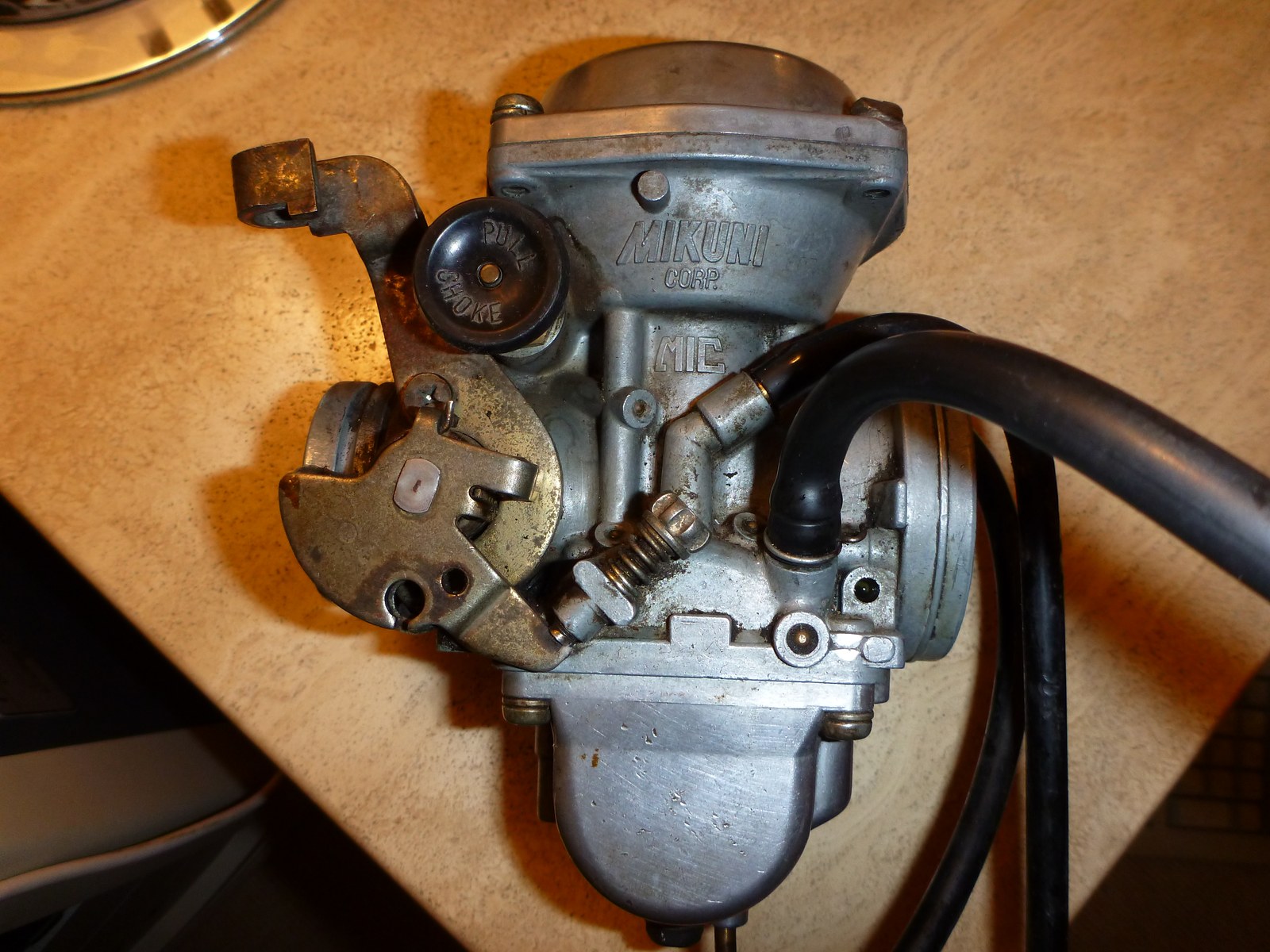
Mikuni BS36SS motorcycle carburettor
Diaphragm constant-velocity (CV) motorcycle carburettor: Mikuni BS36SS from a Suzuki GN400. Photo: Wusel007, Wikimedia Commons, CC BY-SA 3.0.
Mikuni VM-style round-slide mechanical carburettor
Mechanical round-slide example: a Mikuni round-slide carburettor. Photo: Beademung, Wikimedia Commons, CC BY-SA 3.0 DE.
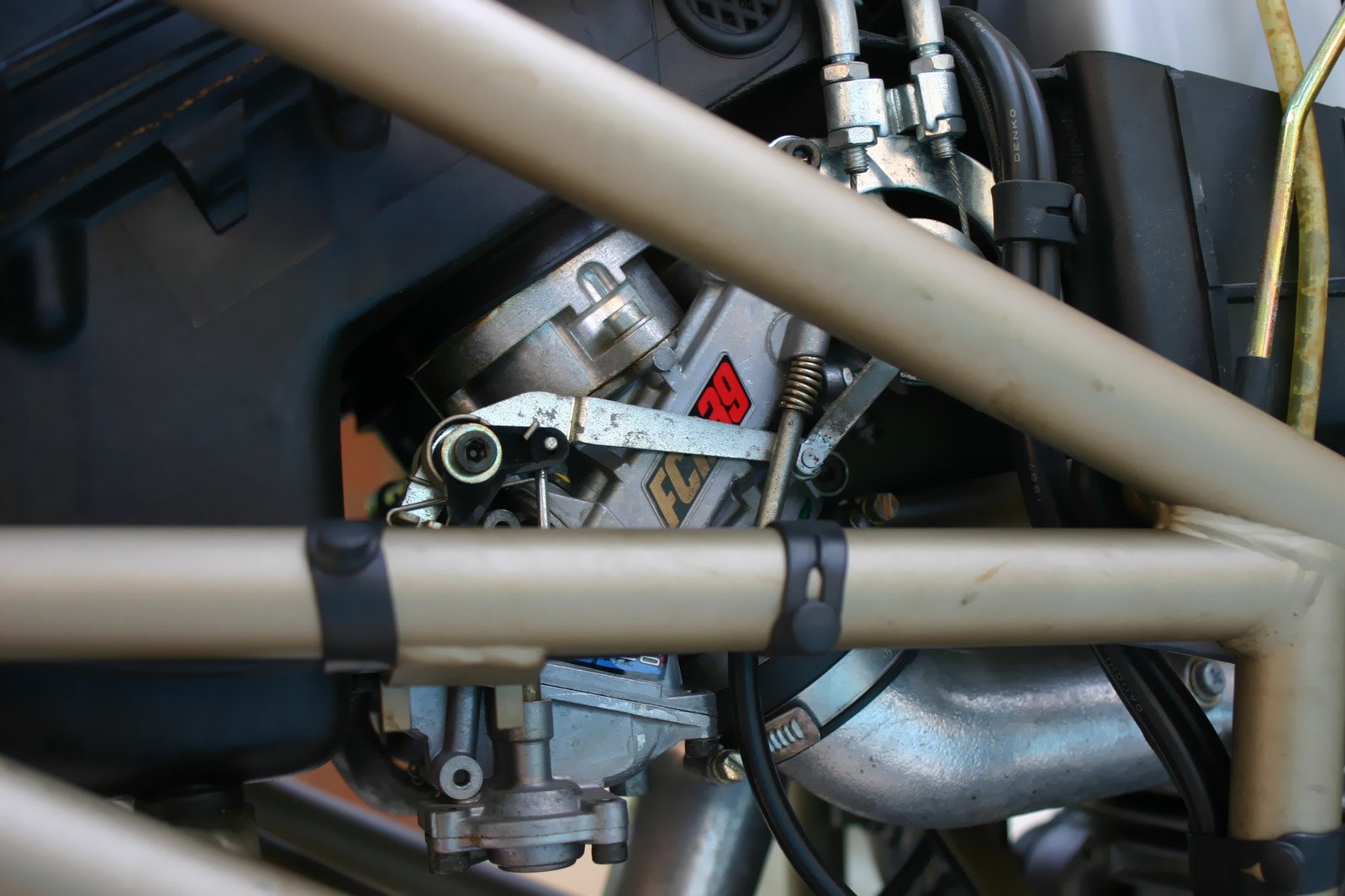
Keihin FCR 39mm flat-slide racing carburettor bank
Mechanical flat-slide example: Keihin 39 mm flat-slide racing carburettors. Photo: andicati; watermark removed by A7N8X. Wikimedia Commons, CC BY 2.0.
Bendix-Stromberg PB-12 B8 floatless aircraft pressure carburettor
Floatless aircraft pressure carburettor: Bendix-Stromberg PB-12 B8 at the Finnish Air Force Museum. Photo: MKFI, Wikimedia Commons, Public domain.

2. Earliest, veteran & vintage carburettor types (1826–1920s)

Before modern venturi fixed-choke and piston constant-depression carburettors matured in the late 1920s and 1930s, pioneers tried several completely different ways to vaporise and meter liquid fuel:

Early type / eraHow it workedInventors, makes & examples
Vapour / evaporative mixer (1826–1880s)Early pre-automotive vapour apparatus heating or bubbling air through volatile turpentine or light spirits to produce a combustible gas mixture.Samuel Morey (1826); Luigi De Cristoforis (1876); Enrico Bernardi (1882 Motrice Pia)
Rotary-brush atomiser (1870s)A pulley-driven revolving brush inside a fuel reservoir dipped into petrol and mechanically flung fine droplets into the intake air stream ahead of the piston suction.Siegfried Marcus (1872 patent / 1875 rotary-brush petrol vehicle)
Surface / bubbling carburettor (1880s–1890s)Intake air passed over the surface of (or bubbled through) a warm brass reservoir of light petrol, picking up vapour by evaporation before entering a mixing slide valve. Sensitive to fuel quality, temperature and road vibration.Karl Benz (1885–1888 patent), early De Dion-Bouton, 1898 Fisson twin-cylinder
Wick carburettor (1893–1900s)Replaced open surface slosh by drawing fuel upward via capillary action into rows of cotton wicks inside an upper vapour chamber; air drew across the saturated wicks and through wire-mesh gauze (an early fuel filter).Dr. Frederick W. Lanchester (1893–1896 Lanchester cars)
Early spray-nozzle & float-feed atomiser (1884–1896)Introduced the float bowl with a needle shutoff valve feeding a spray jet inside a narrowed throat—laying the foundation for almost every float-bowl carburettor since.Edward Butler (1884–1887 "Inspirator" on Butler Petrol Cycle); Wilhelm Maybach & Gottlieb Daimler (1885–1896); János Csonka & Donát Bánki (1893)
Longuemare & "iron-pot" / puddle carburettors (1900–1920s)Early brass/iron float-chamber spray and "puddle" units where fuel pooled in a small trough beneath the air passage or emerged through a slotted spray cone adjusted by a simple needle screw.French Longuemare (licensed by Holley Brothers in 1901), Holley 1904 "iron-pot", Ford Model T Holley three-screw puddle / Holley NH & Kingston L4
Spring-loaded auxiliary air-valve carburettor (1902–1920s)Used a spring-loaded flap or poppet valve to admit extra air as engine suction increased, counteracting the tendency of an uncompensated single jet to go overly rich at high RPM.George Schebler (1902 air-valve patent; Wheeler-Schebler, Marvel-Schebler), Arthur Krebs / Panhard & Levassor (1902)
Leather-bellows variable-choke (1902–1905)Early suction-controlled variable-choke precursor to the modern metal-piston SU: intake vacuum collapsed or lifted a supple leather bellows attached to a tapered metering needle.Early Panhard & Levassor bellows carbs (1902–1904); George Herbert Skinner's prototype SU design (1904–1905)
Twin-lever separate air-and-throttle slide (1905–1928)Pre-Amal motorcycle carbs featuring two independent handlebar levers—one lifting the throttle slide and one lifting a separate air slide—requiring the rider to mix air and fuel manually on the move.Brown & Barlow (B&B), Amac, Binks (merged into Amal in the late 1920s)
Compound-jet / compensating-jet (1907–1930s)Paired a venturi main jet (which grows richer with airflow) with a gravity-fed compensating jet (whose constant flow per second leans out as airflow rises) so the combined delivery stays balanced across RPM.Early 20th-century Zenith (François Baverey's compound-jet design)
1902 Daimler brass float-feed carburettor
Early float-feed carburettor: 1902 Daimler unit. Photo: Wikimedia Commons, Public domain.
1902 Arthur Krebs automatic auxiliary air-valve carburettor patent drawing
1902 Krebs automatic auxiliary air-valve carburettor patent drawing (FR325241 / GB190222655 / US734421A). Credit: A. C. Krebs, Wikimedia Commons, Public domain.

3. By airflow orientation

  • Downdraft: air enters from above and flows vertically downwards into the manifold. Very common on road cars (Weber DGV/IDF, Solex PICT, Holley/Rochester four-barrels) because gravity assists atomised droplets into the plenum and bonnet clearance is easier on V-engines and upright inline engines.
  • Sidedraft (horizontal): air flows horizontally through the carburettor straight into the cylinder-head port. Favoured for multi-carburettor individual-runner performance setups (Weber DCOE, Dell'Orto DHLA, twin SU HS/HIF) because it provides a straight, short inlet path with minimal bends, at the cost of requiring clean float-chamber mounting geometry and careful throttle-linkage synchronisation.
  • Semi-downdraft: tilted slightly downwards (for example 20° to 40° on certain SU HS and HIF installations) to clear inner wings or bonnet lines while preserving the straighter flow of a sidedraft.
  • Updraft: air enters from below and rises into the manifold. Historically common on pre-war cars, stationary engines and tractors where gravity-fed fuel tanks sat above the carburettor and excess liquid fuel drained safely away from the cylinders; rare on post-war performance cars.

4. By barrel count and secondary staging

  • Single-barrel (1V): one venturi and throttle feeding either a shared manifold plenum (Solex 34 PICT, single SU) or a single cylinder (motorcycle slide/CV carbs).
  • Synchronous twin-choke (2V): both throttles sit on a common shaft and open identically together (Weber DCOE, IDF, IDA; Dell'Orto DHLA, DRLA). In a typical four-cylinder dual-carburettor setup, four chokes feed four individual runners (one choke per cylinder) so each cylinder has its own intake pulse and metering circuit.
  • Progressive two-barrel (2V): a smaller primary barrel handles idle, light load and part-throttle cruising with strong air speed, and a larger secondary barrel opens mechanically or by vacuum above roughly half to two-thirds primary throttle (Weber DGV/DGAV, Pierburg 2E2/2E3, Aisan/Hitachi OEM units).
  • Three-barrel (3V): exists in two completely different forms: (1) Honda's stratified-charge Keihin CVCC 3-barrel (two main barrels feeding the main cylinder intake plus a small third auxiliary barrel feeding a rich mixture to the pre-chamber torch-ignition valve on 1970s–1980s Civic/Accord CVCC engines), and (2) the late-1960s Holley 3160 (950 and 1,050 CFM), which paired two primary barrels with one huge undivided oval vacuum-operated secondary butterfly across a standard 4-barrel flange (Hagerty Holley 3160 review).
  • Four-barrel (4V) square-bore vs spread-bore: square-bore carbs (such as the Holley 4150/4160 and Edelbrock Performer/AVS2) use four similar-sized throttle bores; spread-bore carbs (such as the Rochester Quadrajet and Carter Thermoquad) pair small primary bores for crisp low-speed signal and economy with very large secondary bores for top-end flow.
  • Multi-carburettor staged racks ("Tri-Power" / "Six Pack" / "Dual Quad"): factory and hot-rod manifolds pairing three two-barrels (such as 3×Holley 2300 on Chrysler 340/440 Six Pack or 3×Holley 1904/1908 inline-six kits, where the centre carb runs idle/cruise and outer carbs open progressively) or two four-barrels (Chrysler Street Hemi 2×Carter AFB).
  • Vacuum vs mechanical secondaries: on four-barrels, vacuum secondaries sense primary venturi airflow through a diaphragm so the secondary throttles only open as far and as fast as the engine can actually ingest air—avoiding the bog caused by opening too much area too early on heavy vehicles or automatic transmissions. Mechanical ("double-pumper") secondaries open directly via linkage and include a second accelerator pump to cover the sudden pressure drop when all four bores open together. See Holley 4160 installation instructions and Holley secondary diaphragm spring tuning.
Holley square-bore four-barrel performance carburettor
Square-bore four-barrel example: a Holley four-barrel performance carburettor. Photo: Rich Niewiroski Jr., Wikimedia Commons, CC BY 2.5.
Rochester Quadrajet M4ME spread-bore four-barrel carburettor
Spread-bore four-barrel example: a Rochester Quadrajet M4ME showing small primary and large secondary bores. Photo: Craigblock, Wikimedia Commons, Public domain.

5. Forced-induction layouts: draw-through vs blow-through

Combining a carburettor with a turbocharger or supercharger changes the pressure reference around the float chamber:

  • Draw-through: the carburettor sits upstream of the compressor, so the carburettor itself always sees atmospheric pressure at its inlet and vacuum below the throttle. Traditional Roots-type superchargers and early carburetted turbos used draw-through layouts, which must be paired with a turbocharger carbon-face compressor seal capable of withstanding high throttle-closed manifold vacuum without drawing oil into the intake, and cannot normally run an intercooler downstream of the compressor because wet fuel mixture would puddle in the core.
  • Blow-through: the carburettor sits downstream of the compressor (and any intercooler), so boost pressure fills the carburettor throat. If the float bowl remained vented only to atmosphere, boost pressure would push fuel back down the jets and starve the engine immediately. A blow-through conversion therefore requires: (1) referencing the float-bowl vents and fuel-pressure regulator 1:1 to bonnet/hat boost pressure so differential fuel pressure stays constant; (2) solid or nitrophyl floats that will not collapse under boost pressure; (3) sealed throttle shafts and gaskets; and (4) a boost-referenced power valve or enrichment circuit, because normal manifold vacuum stays low or positive under boost (Holley/Weiand supercharger carburetion reference).

Adjustment diagrams for selected carburettor models

The linked illustrations identify controls on particular carburettors. Screw locations, functions and part numbers can change between models and diagrams; match the carburettor and use the key beside each drawing.

  • Solex 30 PICT-3 and 34 PICT-3: EMPI's Solex service instruction sheet, exploded view and key, identifies the air-bypass screw as item 31 and the volume-control screw as item 35. The sheet covers other variants too; its idle-setting procedure distinguishes the PICT-3 from the PICT-2.
  • Pierburg 2E3: the Pierburg 2E3 service manual has an opening exploded view identifying the fast-idle adjuster as 1 and the mixture adjuster as 3. In the separate idle-correction illustration on page 3 the throttle-plate screw is 1 and mixture screw is 4: these two drawings use different number keys. The manual says screws with tamper-proof caps or protective lacquer are not to be adjusted.
  • Jikov 2928CE: CVKustoms’ 2928CE illustrated reference, figure 1 reproduced from the Jawa 350/640 manual, identifies the idle-adjust screw as 9 and the mixture-adjust screw as 10. The later adjustment illustration uses a different number key; other Jikov models may differ.
  • Bing constant-depression carburettors on BMW R75/5–R100: Ulis Motorradladen’s parts catalogue, group 13c, identifies the mixture-regulating screw as item 6 and the butterfly-adjusting screw as item 9 in its exploded drawing. This illustration applies to the listed BMW applications, not all Bing models.
Simplified Solex 34 PICT-3 left side showing large upper air bypass and small lower volume control screws
Solex 34 PICT-3: the larger upper screw adjusts idle bypass air; the smaller lower screw adjusts idle mixture. Simplified drawing prepared for Tuning Wiki using SteelyTim’s photograph (adapted, CC BY-SA 4.0) and the Solex parts diagram (bypass 31; volume control 35). Match the carburettor model before applying the diagram.

Related pages

Sources