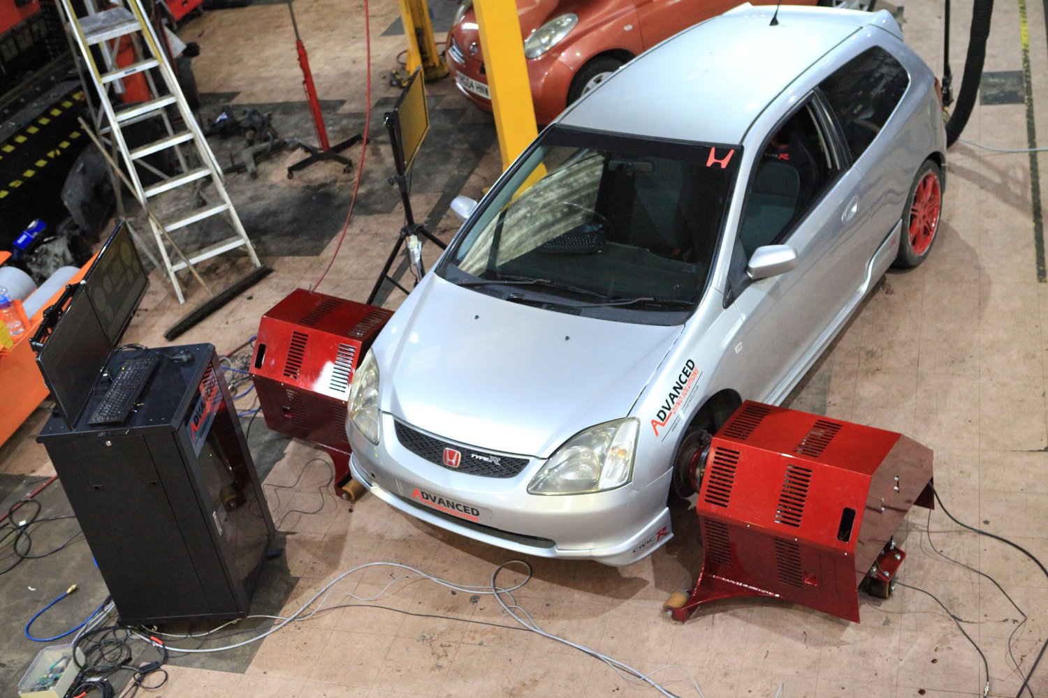
A hub dynamometer tests a vehicle with its driven road wheels removed and dynamometer units attached to the wheel hubs using vehicle-specific adapters. The engine, transmission and final drive remain in the vehicle. The units resist hub rotation and measure or infer the resulting torque and speed. This avoids the tyre-to-roller contact of a rolling road, while transmission and differential losses remain in the measurement boundary. Hub output is not direct crankshaft output.

Principle of operation
Each driven hub turns a coupling and absorber. Depending on the design, braking may be hydraulic, eddy-current or electrical. Torque can be measured with a calibrated reaction arm and load cell or an inline torque sensor, and shaft speed with an encoder. Power for each measured shaft is torque multiplied by angular speed; total output is the sum of the shaft powers, with the correct sign and any applicable correction. A controller changes absorber demand to hold speed, regulate load or run an acceleration test.
Hub-coupled dynamometers also appear in development rigs with separate control of each axle or wheel. The method can simulate drivetrain loads and wheel-speed differences when the machine and control strategy support them; it should not be assumed that all workshop hub dynos can do this. SAE 2011-26-0045: dynamic drivetrain testing; SAE 881736: four independent axle dynamometers.
Advantages and limitations
There is no tyre slipping, changing tyre pressure or tyre deformation against rollers during the measurement. This helps when a high-torque vehicle is difficult to run consistently on tyres. Removing wheels and fitting adapters takes time, and compatible adapters, mounting hardware, hub loads, driveline angles and speed/torque ratings must be checked. The vehicle and units must be supported and restrained as the equipment maker specifies. The exact result also depends on coupling losses, sensor calibration, control response and the inertia being accelerated.
Four-wheel-drive and control
Use the required number of units and the configuration prescribed for the particular vehicle and dyno. All-wheel-drive couplings, differentials, traction control and electric axles can respond to unexpected wheel-speed differences. Four independent channels can emulate different wheel loads only within the capabilities of their software, absorbers and vehicle installation. Consult both manufacturer's procedures.
Reporting and comparison
Identify measured hubs, gear, speed source, calibration, temperatures, applied correction and whether the result includes any estimated drivetrain loss. A direct comparison with roller wheel power must allow for the tyre/roller interface that a hub system omits. Repeat a baseline on the same installation and conditions when assessing a calibration change.
Manufacturer examples
Advanced Dyno Solutions’ 2WD hub system is described with two eddy-current brakes and interchangeable hub adapters. Dynocom’s AWD 4500 is an example with four eddy-current pods. Check adapter compatibility, equipment ratings and the manufacturer’s operating procedure for the specific vehicle.
See also: Dynamometers overview · Rolling roads · Engine dynamometers · Hub dynamometers · On-car and portable systems · Inertia dynamometers.