D2B, the digital data bus, is Mercedes-Benz's optical ring for the radio, CD changer, telephone, voice control and Tele Aid. Light carries the audio and the commands. A separate copper wire wakes the ring. Diagnosis is through the radio or COMAND, which is also the gateway to CAN. It is the ring MOST later replaced on the models Mercedes lists, and it is not the engine bus.
The account follows Mercedes function description GF82.00-P-0001A of 23 March 1998, including the data-transmission, wake-up and fibre sections printed with it, and the Mercedes-Benz USA training sheet 416 HO MOST of 1 July 2004, which compares D2B with the MOST ring that followed. A model year or a part on one of those sheets belongs to the cars that sheet covers. The later optical ring is on the MOST optical bus page. How D2B sits beside MOST and BMW's safety fibre is on the fibre-optic networks page.
Where Mercedes fitted it
GF82.00-P-0001A applies the bus to model series 129 from 1 June 1998, 163, 168 from 1 September 1998, 170, 202 from 1 June 1998, 203, 208, 210 from 1 June 1998, 215 and 220. Those numbers are the document's. The same page draws a model 220 ring as radio Audio 30, CD changer, voice-control module, telephone transmitter-receiver and Tele Aid, and it shows the diagnostic data-link connector X11/4 on that illustration. The diagnostic connector is the electrical workshop socket. The tester does not join the fibre.
The ring order is model-specific, and the radio or COMAND is always first. The 1998 description gives two examples. On a 210 the order is radio, CD changer, voice control, telephone, Tele Aid. On a 202 it is radio, CD changer, telephone, voice control. The factory sequence is stored in the radio or COMAND. Fitting a radio from one of those examples into the other stores a fault, because the sequence no longer matches, and so does fitting a radio into a car of the same series whose options differ, such as a 210 with a CD changer and a 210 without one. The ring still goes to the operational state. The hand-held tester can rewrite the sequence afterwards.
The 2004 training sheet, which warns that its model list is preliminary, puts the change to MOST at the start of 211 production for model year 2003, then names further series through model year 2006. It also says the SLR was to be introduced on D2B, with no plan at that date to move it. That is the sheet's statement in 2004. It is not a survey of every later car.
The ring and the frame
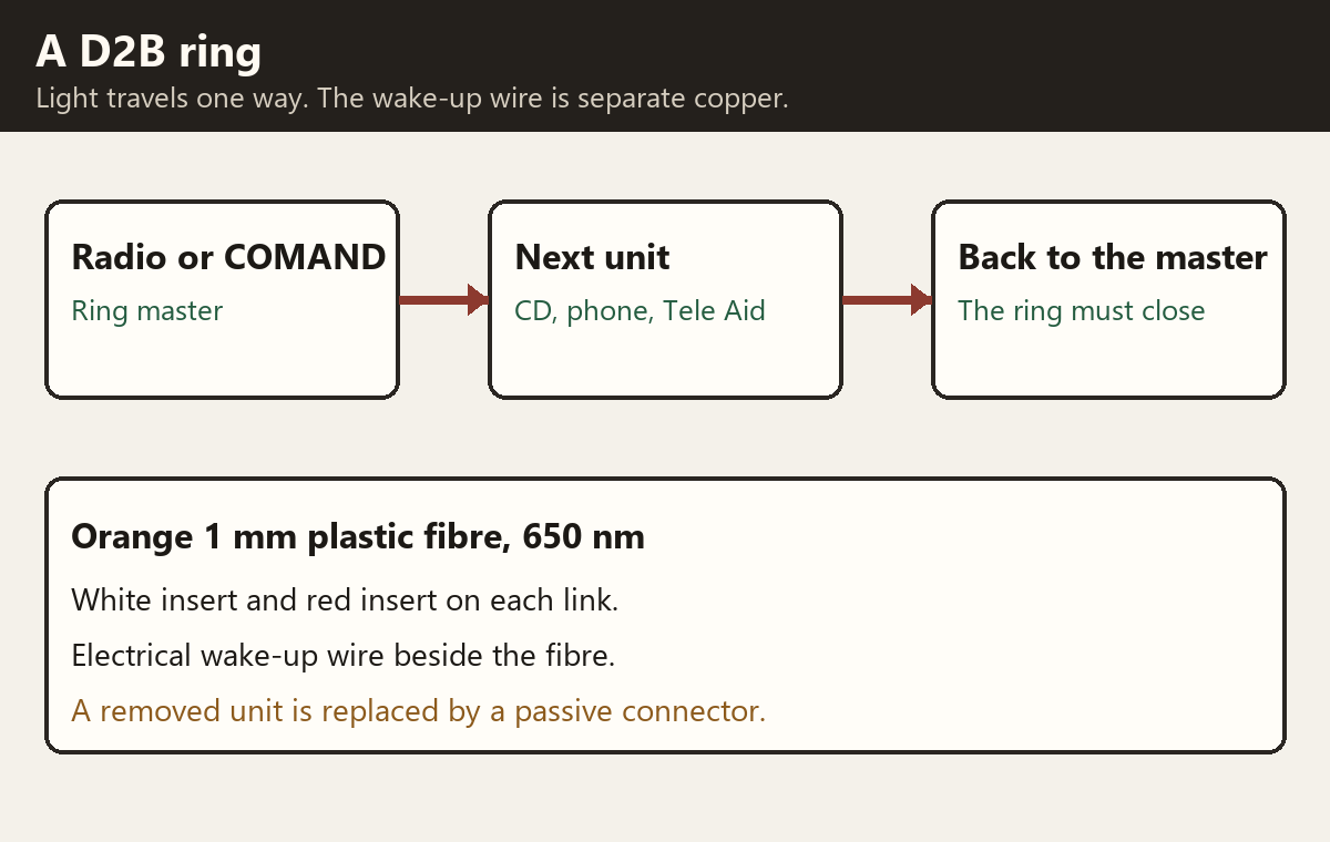
The bus is a closed ring. Information moves in one direction, so a command for a unit further round the ring passes through the units in between. The radio or COMAND is the master. The other units are subordinates. The master is the clock. A frame is two subframes, and a run of frames carries what the telephone, the changer and the rest of the ring need.
Each unit has an optical transmitter and an optical receiver. Inside the unit a D2B chip speaks the protocol. Source data, such as the music from the CD, is synchronous: the description puts it in the subframes as 32-bit blocks, in the form it has on the disc. Control data, such as Play, is asynchronous: two bits per subframe, spread across many subframes, each packet carrying an address for the unit it is meant for. The receiving unit reassembles the packets. One frame can therefore hold source data and control data from every unit on the ring at once. Whatever a unit was sent, it puts a fresh light signal back onto the bus at full intensity. That repeater is why the next hop starts from a full signal again.
The master is also the gateway to the CAN bus. Signals are converted in the master so that D2B and CAN can exchange them. The 2004 sheet names that CAN as CAN B, and names the radio or COMAND as both the bus master and the diagnostic interface.
The fibre
The fibre is synthetic, 1 mm in diameter, with orange insulation against damage and outside light. The wavelength in the 1998 description is 650 nm. Attenuation depends on the length between units, the bend radii, damage or pinching of the insulation, and the passive connectors. The minimum bend radius in that description is 25 mm. The 2004 comparison repeats 25 mm for D2B and, for MOST, only the instruction not to kink the fibre.
The same description gives the two ends different inserts. The white insert is the fibre-optic cable input, and the sentence also calls it the control-module output. The red insert is the fibre-optic cable output, and the sentence also calls it the control-module input. The location figure on that page labels the inserts white and red. Those two clauses are the document's own pairing. Use the wiring figure for the car in front of you when the wording and the plug can be read more than one way.
The 2004 sheet adds length limits that the 1998 function page does not: 33 ft with no in-line connector, and 10 ft when three in-line connectors are fitted. It also caps a D2B ring at 6 devices, against 64 for MOST, of which that sheet says Mercedes could then configure 16. Its rates are "up to 5.65 Mbit/s" for D2B and "up to 24.8 Mbit/s" for MOST. The later MOST specification summary calculates MOST25 as 22.58 Mbit/s. The 5.65 and the 24.8 are the 2004 sheet's figures. They are not a second measurement of the MOST book.
Wake-up, and finding a break
Transmitter, receiver and the D2B chip switch off when they are not required. The 1998 description says that happens as soon as the master or the ignition is switched off. Starting again needs the electrical wake-up wire. The master drives that wire so its voltage falls to a defined value. The chip in each unit recognises the duration and brings the ring up. A sleeping ring can also be woken without the master, and the description's example is the telephone adapter on an incoming call.
If the optical ring will not start, the master can send a diagnostic wake-up from the hand-held tester or from Star Diagnosis. That pulse is much longer. Each unit answers on the wake-up wire, so the master can see which units received it. If every unit answers, their power supply is intact. The description excludes this diagnostic wake-up on models 203, 215 and 220 when they have the Mercedes radio Audio 30, code 750a.
An open ring is repaired, for test or for a missing unit, by closing it. The fibre section calls the piece that does this a passive connector, used when a failed component is removed so the remaining units can still work. The 2004 sheet lists a passive fibre connector for D2B testing and a different one for MOST, and it says a Berger fibre tester can be used on D2B and cannot be used on MOST. The sheet's part numbers are split across table cells, so they are not repeated here. The principle is the same one used later on MOST: the loop is a piece of fibre in the ring, and the removed unit is off the ring.
Diagnosis of the bus itself is through the radio or the COMAND. A fault in the stored sequence is a configuration fault. A ring that will not light is chased on the wake-up wire first, because that test is only offered when the optical ring cannot be activated, and then by closing the fibre around one unit at a time.
What MOST changed
The 2004 sheet calls MOST an evolution of this fibre ring and its electrical wake-up, and a standard written by DaimlerChrysler, Becker and others, where D2B had been Mercedes' own. On the MOST cars in that sheet the master becomes the Audio 20 head unit or the audio gateway, the gateway to CAN B moves with it, and wake-up can be electrical or optical. The fibre, the one-direction ring and the need to close a gap remain. The speeds, the device count, the length and the workshop tester do not. Those differences are the sheet's comparison, not a claim that every later Mercedes ring is the 2004 MOST.
Sources
- GF82.00-P-0001A, Digital data bus (D2B), function, 23 March 1998, with GF82.00-P-2000A, GF82.00-P-2001A and GF82.00-P-4000A. Model list, ring order, frame, 650 nm, 25 mm, wake-up and the passive connector. Read from a WIS mirror. Accessed 2026-11-12.
- 416 HO MOST, Mercedes-Benz USA technical training, 1 July 2004. D2B against MOST: 5.65 Mbit/s, six devices, fibre lengths, Berger tester, and the preliminary model list. Accessed 2026-11-12.
- The MOST optical bus. The specification rates that the 2004 sheet's 24.8 Mbit/s should not be collapsed into.