An ignition distributor is the shaft-driven unit that, on a single-coil spark-ignition engine, routes the coil's high tension to each spark plug in firing order. On older engines it also decides when the spark happens: a cam and contact breaker, or an electronic pickup, switches the coil, and centrifugal weights and a vacuum unit move that switching point with speed and load. Engine-management systems from the 1980s onward moved the timing decision into a control unit. In those systems the distributor became a sensor housing and a high-tension switch, and distributorless systems later removed it altogether. This page covers what a distributor contains, the trigger types and integrated designs, and how to identify them. The advance mechanisms, servicing and ECU conversions have their own pages, listed under Related pages.

What a distributor does
The distributor shaft turns at camshaft speed, half crankshaft speed, because each cylinder fires once per four-stroke cycle of two crank revolutions. On most overhead-valve engines a gear on the camshaft drives the shaft, and the same gear often drives the oil pump. On most overhead-camshaft engines the shaft is coupled to the end of a camshaft by an offset dog or tang, so it can only be fitted one way round. One turn of the distributor is therefore one complete engine cycle, and every angle measured on the distributor is half the matching crank angle. A 10° movement of the distributor body moves the timing 20 crank degrees.
A conventional distributor does two jobs. It triggers the coil once per cylinder, through the cam and points or a pickup. It also distributes the resulting high-tension pulse, through the rotor and cap. In a fully mechanical system it adds a third: the advance mechanisms set the timing. Where an ECU calculates the timing, the distributor keeps only the distribution job, and often carries the crank- or cam-position sensor that the ECU uses as its reference. Bosch's term for this is rotating high-voltage distribution, as opposed to the static distribution of wasted-spark and coil-on-plug systems.
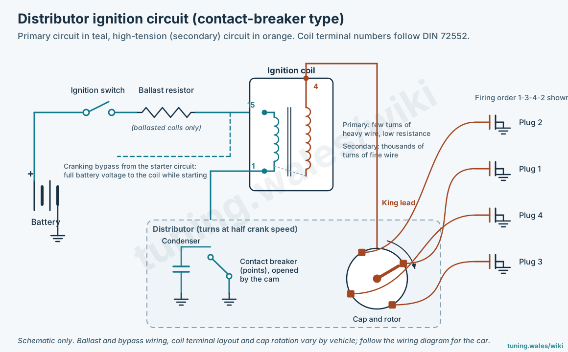
Cap, rotor and high-tension path
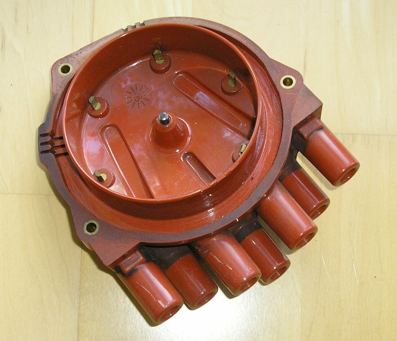
The coil's high tension enters the centre tower of the cap and reaches the rotor through a spring-loaded carbon brush. The rotor tip passes close to, but does not touch, a metal insert inside each side tower. The spark jumps that rotor gap and then travels down the plug lead. Bosch's aftermarket literature describes caps as carrying up to about 30,000 V. It says the arc at the rotor generates heat and a large amount of nitrogen oxides, so cap and rotor materials need high resistance to chemical attack and to tracking. Many caps and rotors are fibreglass-reinforced polyester with a sealed surface. Some rotors also carry a centrifugal speed limiter, which shorts the high tension to earth above a set speed.


The rotor gap is a second spark gap in series with the plug, so part of the coil's output is used before the plug fires. No production figure for the voltage that gap consumes has been published in the sources reviewed. A General Motors patent filed in 1978 gives one laboratory example: a 3 mm distributor gap that broke down at 20 kV, reduced to 8 kV with a silicone dielectric coating, and radio interference that became excessive when gap breakdown exceeded 12 kV. Those are patent test conditions, not service values. Secondary-ignition analysis guidance lists a wide rotor gap as a cause of high firing lines, crossfire inside the cap as a cause of a long, low spark line, and a bent shaft or worn bushes as a cause of uneven firing voltages.
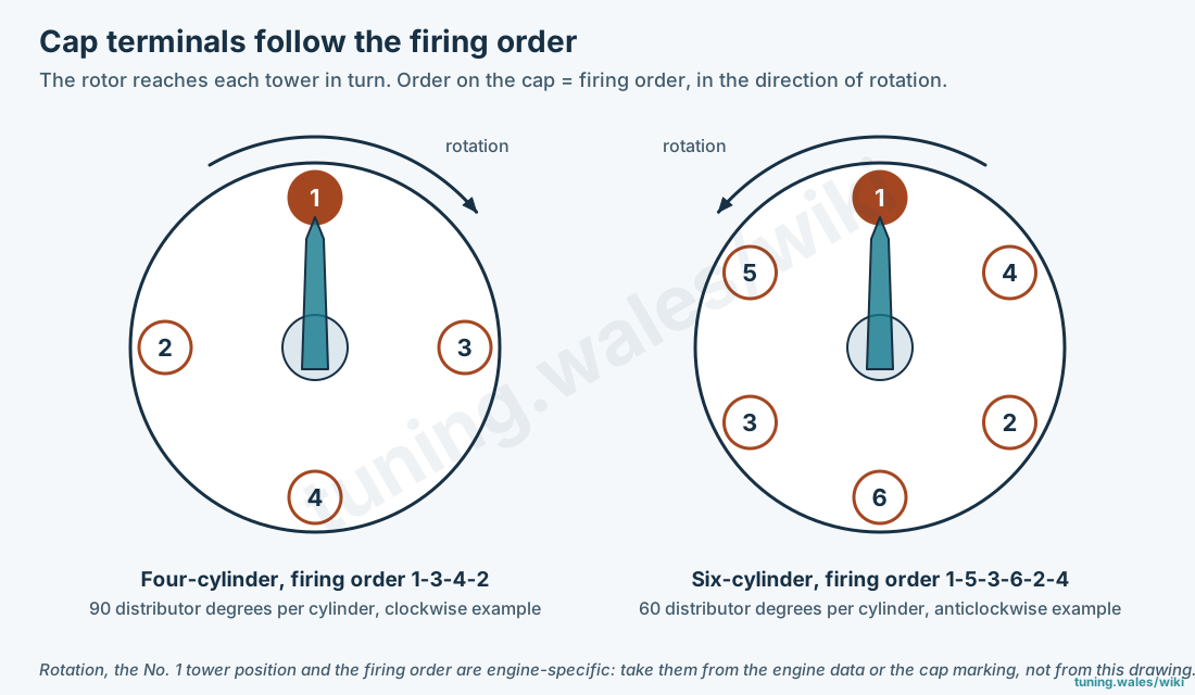
Cap order and firing order
The towers are connected in the engine's firing order, in the direction the rotor turns. Each cylinder owns an equal share of the rotor's travel: 90 distributor degrees on a four-cylinder, 60 on a six and 45 on an eight. Rotation direction and the position of the No. 1 tower vary by engine, and many caps have No. 1 moulded on the tower. A cap with the leads one tower out in either direction will not run the engine, and a cap fitted the wrong way round on a distributor where it can be indexed two ways reverses the order.
Trigger types
The trigger is whatever decides the moment the coil current is broken. Four kinds are found inside distributors.

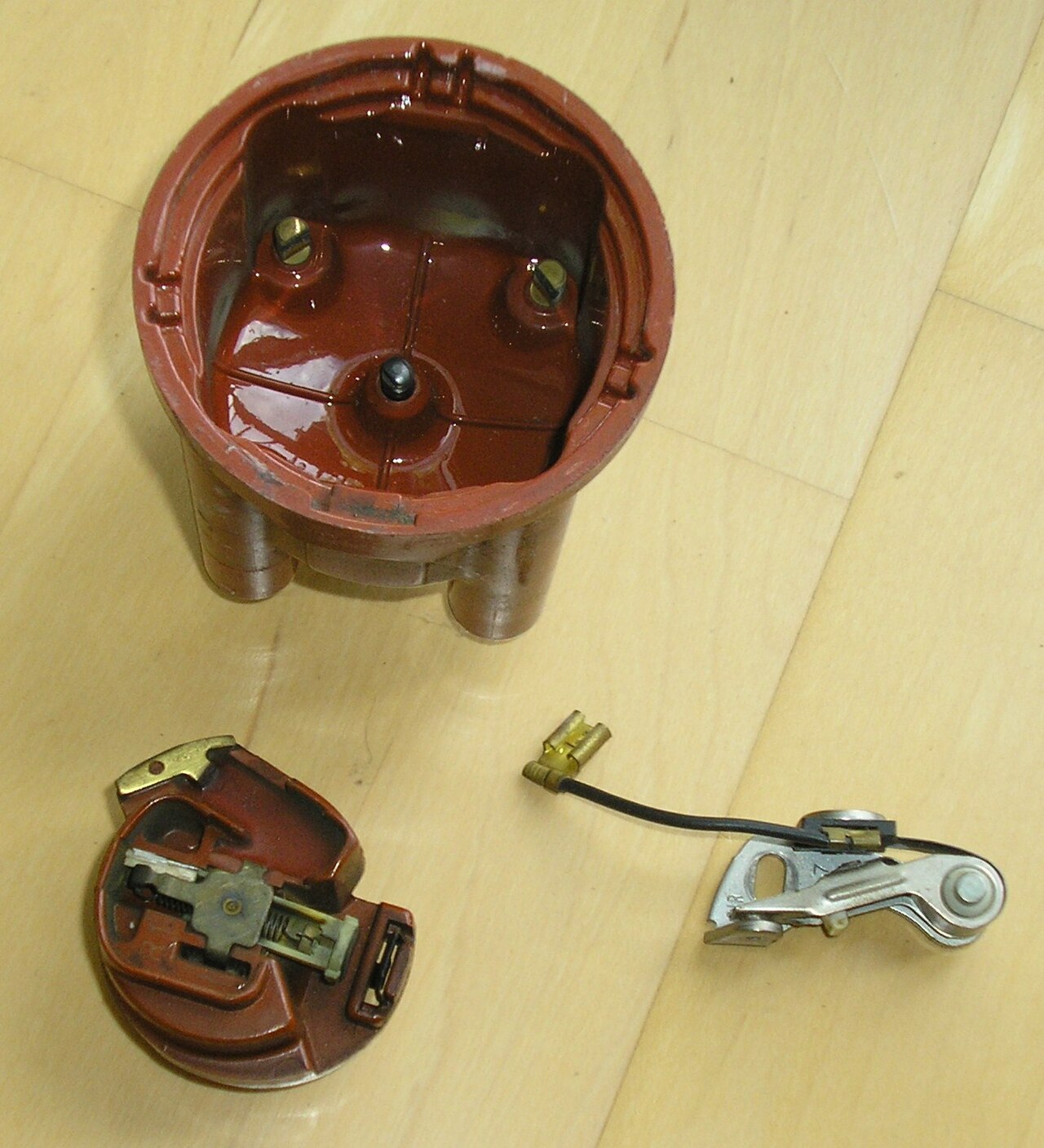

- Contact breaker and condenser. A cam with one lobe per cylinder opens a spring-loaded switch in the coil primary. The condenser (capacitor) across the points absorbs the primary current as they open, so the field collapses quickly and the contacts do not arc away. Manufacturer figures cluster around 0.2 µF: 0.18–0.24 µF in Lucas training material, 0.18–0.23 µF in a 1969 Buick (Delco) service manual, and 0.20–0.25 µF on a 1930 Ford drawing. Point gap, dwell and wear are covered on the servicing page.
- Inductive (magnetic, reluctor) pickup. A toothed reluctor on the shaft passes a coil wound on a permanent magnet. The output is an alternating voltage whose amplitude rises with speed, and an ignition module switches the coil near a zero crossing. Examples include the Bosch TSZ-i, which Opel applied to its 1.2 and 1.3 litre engines from August 1982 and which allowed the switching module to be mounted on the distributor, GM's HEI and Ford's Duraspark. For the HEI pickup, enthusiast and parts-trade sources give 500–1500 Ω across the terminals and no continuity to earth; no GM manual figure was located.
- Hall-effect sender. A rotor with one vane or window per cylinder passes between a permanent magnet and a Hall integrated circuit. The output switches between two fixed levels regardless of speed, so the signal is usable from a standstill. The Bosch TSZ-h distributor is the common European example: a four-window rotor on four-cylinder engines, a three-wire connector, retained centrifugal and vacuum advance, and no condenser. Ford's TFI-IV distributors used a Hall stator to produce the profile ignition pickup (PIP) signal for both the module and the EEC-IV engine computer.
- Optical. A slotted disc interrupts a light beam between an LED and a photodiode. Nissan's crank-angle sensors, built into the distributor or a distributor-shaped housing on engines such as the L28ET, VG30E/ET, KA24E and SR20DE/DET, use a disc with 360 slits for 1° resolution and one further slit per cylinder for reference. GM's LT1 Opti-Spark (from 1992) reads 360 outer slots and eight inner slots of differing widths. The aftermarket Lumenition kit, from Autocar Electrical Equipment, fits an infrared beam and a chopper with one blade per cylinder to an existing points distributor; a beam-controlled ignition from that company was reported at the 1969 Motor Show.
Lucas's OPUS system, used on Jaguar V12 and Aston Martin V8 engines from about 1971, used an oscillator and a ferrite-cored pickup sensing ferrite pieces on the rotor, and was replaced by Lucas constant-energy ignition around 1980. Those dates come from enthusiast and supplier sources and have not been checked against Lucas or Jaguar documents.
Integrated distributor designs
Several manufacturers moved the coil, the switching module or both into the distributor itself. Identifying which design is fitted decides what can be tested separately and what an ECU conversion has to replace.
| Design | What is in the distributor | Notes |
|---|---|---|
| GM / Delco-Remy HEI | Magnetic pickup and control module; on most applications the coil sits in the cap | Standard on GM North American cars from the 1975 model year, optional during 1974. Large cap to separate the terminals at up to about 35 kV. Modules exist with 4, 5, 7 and 8 pins; the 7- and 8-pin versions work with timing commanded by the engine computer. |
| Ford TFI-IV | Hall stator and, on early versions, the six-pin module on the distributor base | Used with EEC-IV from 1983. PIP is a 50% duty-cycle square wave. Later versions moved the module to a remote mount. Coil is external (E-core). |
| Toyota IIA (integrated ignition assembly) | Igniter and an open-type coil combined with the distributor | In use by 1982 on the Starlet 4K-C according to the reproduced Toyota manual; introduction year not established. |
| Honda (PGM-FI era) | TDC, CRANK and CYL sensors stacked on the shaft; on many 1992–2000 Civic distributors also the coil and igniter | The ECU calculates timing. Turning the distributor moves the sensor reference rather than the spark directly. Earlier carburettor systems had one pickup and an igniter on the side of the housing, with mechanical advance. |
| Nissan optical crank-angle sensor | LED/photodiode pair and a 360-slit disc with reference slits | Gives both crank angle and cylinder reference to the ECU. Reference-slit widths differ between engines. |
| GM Opti-Spark (LT1) | Optical sensor plus cap and rotor, mounted at the front of the engine below the water pump | External igniter. Water-pump leaks and moisture are the widely reported failure cause; vented versions followed in about 1994–95 (sources disagree on the exact change point). |
| Bosch Motronic and similar | Usually only cap and rotor, sometimes on the end of a camshaft | Timing calculated by the ECU from a crank sensor; the distributor is a high-tension switch only. |
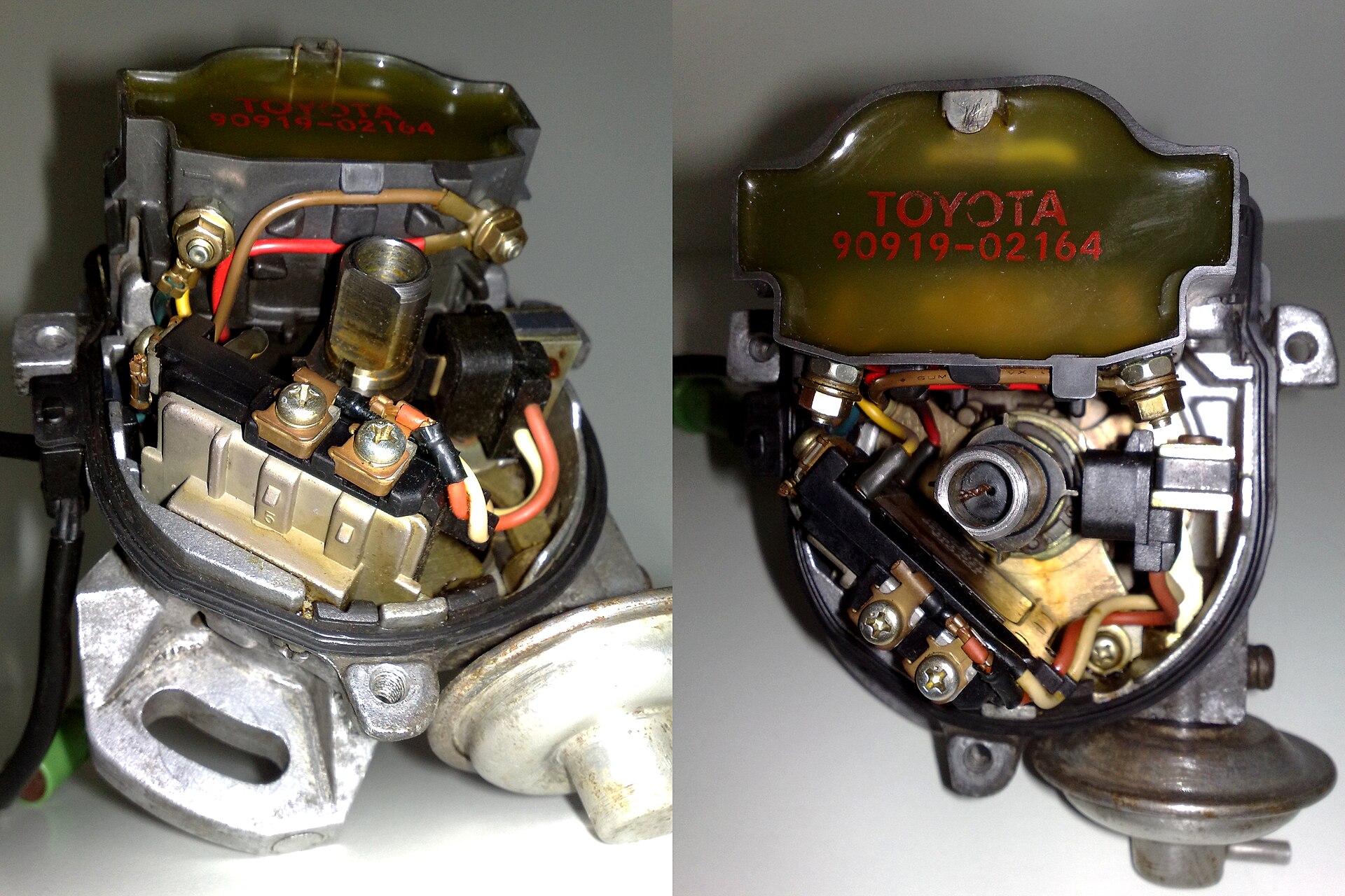


Advance mechanisms
A distributor that sets its own timing combines three parts: the static or initial setting made by turning the distributor body, centrifugal advance from weights on the shaft, and vacuum advance from a diaphragm that turns the breaker or pickup plate. How each part behaves, how curves are specified in distributor degrees, and how they are measured and altered is described in Distributor advance: centrifugal and vacuum. The reasons the spark has to move with speed and load are in Ignition tuning.
History and replacement
Charles Kettering's battery ignition, with a coil, an interrupter and a rotating timer arm, was filed as a US patent on 8 November 1910 and assigned to the Dayton Engineering Laboratories Company (Delco). Cadillac ordered the system in 1909; sources disagree on whether it reached production on 1910 cars or first on the 1912 Cadillac, where it was combined with Kettering's electric starter. The coil-and-distributor layout remained the norm for petrol cars for most of the century.
Distributorless systems displaced it from the mid-1980s. GM's C3I wasted-spark system appeared in 1984 on the Buick 3.8 litre turbocharged engine. Saab put capacitor-discharge Direct Ignition, with a coil per plug, into production on the 9000 in 1988. Ford introduced a distributorless system with Hall sensors in 1989 and EDIS, with a variable-reluctance crank sensor, in 1991 (one listing dates EDIS-4 to the 1988 Escort, which conflicts). SAE J1930 later renamed DIS as electronic ignition (EI). Coil-on-plug became the common layout from the early 2000s. Distributors remain in service on classic cars, on many engines converted to standalone management, and in motorsport classes that require them.
Identification checklist
- Count the low-tension wires to the distributor body. As a rule of thumb, which the wiring diagram should confirm: one wire from the coil negative is points; two wires is usually an inductive pickup; three is usually a Hall sender; a multi-pin connector suggests stacked sensors or an integrated module; no low-tension wire at all, only high-tension leads, is a cap-and-rotor unit on an ECU-timed engine.
- Remove the cap and look under the rotor for points, a toothed reluctor, a vane cup or a slotted disc.
- Check for a vacuum unit and for weights under the plate. Their absence on a car with an ECU usually means the ECU sets the timing.
- Note the number stamped on the body or a tag. Bosch units carry a ten-digit part number; Lucas units carry a type (such as 25D, 45D or 59DM) and a service number. Advance curves and dwell figures are published against those numbers, not against the vehicle alone.
Related pages
- Distributor advance: centrifugal and vacuum
- Distributor servicing, timing and fault diagnosis
- Distributors with ECU-controlled timing: locking advance and rotor phasing
- Ignition systems and spark plugs, for magnetos, wasted spark, coil-on-plug and dwell windows
- Ignition coils, dwell and driver compatibility
- Crankshaft and camshaft position sensors
- Automotive timing lights
Not established
- A manufacturer figure for the voltage consumed by a production rotor gap, and standard gap dimensions.
- Resistance specifications for Bosch inductive and Lucas 59DM/65DM pickups, and the Bosch Hall sender supply voltage.
- Manufacturer confirmation of the Lucas OPUS dates and the Toyota IIA introduction year.
Sources
All accessed 2026-11-19.
- Robert Bosch GmbH, Ignition components, aftermarket brochure AA-TR/PAG 2018/11. Manufacturer document: cap voltage, cap and rotor materials, nitrogen oxides and tracking, speed-limiting rotors, inductive and Hall distributors.
- General Motors, US patent 4,186,286, filed 10 October 1978, granted 29 January 1980. Laboratory rotor-gap breakdown figures.
- MOTOR magazine, Secondary ignition analysis, May 2001. Rotor gap, crossfire and bushing-wear scope patterns.
- Joe Woods, "Conventional" Honda ignition, Import Service, December 1999. Honda distributor sensors, igniters and cap inspection.
- Ford Garage, Condenser capacitance. Enthusiast site quoting 1928 and 1930 Ford documents.
- Joseph Lucas Ltd, Lucas coil ignition – training, c.1950s, transcribed by the Jowett Car Club of Australia, 17 February 2018. Manufacturer training text: condenser capacity.
- Buick, 1969 chassis service manual, ignition system. Manufacturer documentation: condenser capacity.
- Ford Sierra workshop manual, distributor description (translated reproduction). Bosch Hall distributor construction.
- Opel Kadett D workshop manual, TSZ-h and TSZ-i (translated reproduction). Hall and inductive systems, module on the distributor, August 1982 application.
- 73-87.com, HEI pickup coil test. Enthusiast source for the 500–1500 Ω range.
- Nissan 300ZX VG30ET crank angle sensor description (reproduced service information). 360 slits and reference slits.
- DIYAutoTune, Nissan optical trigger discs. Vendor article: engine applications.
- Haltech, LT1 350 Gen II engine. ECU-maker note: Opti-Spark slots, location, vented versions.
- Commercial Motor, Beam controlled ignition, 21 November 1969. Autocar Electrical Equipment infrared ignition.
- Wikipedia, High energy ignition, citing SAE paper 750346. HEI layout, voltage and introduction.
- Wikipedia, Distributor. Drive arrangements; partly uncited.
- kfz-tech.de, LE-Motronic, September 2009. Distributor reduced to high-voltage distribution.
- K. Reif (ed.), Gasoline Engine Management, Bosch Professional Automotive Information, Springer, 2015, DOI 10.1007/978-3-658-03964-6. Rotating and static high-voltage distribution (consulted as search extracts only).
- Engineering and Technology History Wiki, Charles F. Kettering. Cadillac order and 1912 starter; Kettering US patent 1,170,275, filed 8 November 1910.
- Craig Nangle, GM DIS – Part I, Motor Age / FenderBender, 1 January 2020. GM C3I in 1984 and SAE J1930 terminology.
- Jacques Gordon, Vehicle Service Pros, 7 April 2015. Ford DIS in 1989 and EDIS in 1991.
- Wikipedia, Saab Direct Ignition. 1985 presentation and 1988 production.
Diagrams on this page are original Tuning Wiki drawings and are schematic. Photographs are from Wikimedia Commons under the licences given in each caption.