The high-output 3.0-litre M57 uses BMW's Variable Twin Turbo (VTT), a regulated two-stage system with differently sized turbochargers. This guide covers the M57-based 535d, 335d, X5 3.0sd/xDrive35d and X6 xDrive35d. Model badges alone do not identify an engine: later vehicles and different markets can use other diesel engines and emissions systems. Check the VIN, build date and engine identification before ordering parts or applying specifications. See the M57 engine family.
Applications and output
| Application | Representative factory rating | Notes |
|---|---|---|
| E60/E61 535d, original M57D30TÜ TOP | 200 kW (272 PS; 268 bhp) at 4,400 rpm; 560 Nm at 2,000 rpm | First 535d VTT generation, introduced in 2004. |
| Later E60/E61 535d, M57D30TÜ2 TOP | 210 kW (286 PS; 282 bhp); 580 Nm | Updated aluminium-block engine; market and production date matter. |
| E90/E91/E92 335d | 210 kW (286 PS; 282 bhp); 580 Nm | European specification; the US 335d had a different rating and emissions configuration. |
| E70 X5 3.0sd / xDrive35d | 210 kW (286 PS; 282 bhp); 580 Nm | European 3.0sd launch rating; later naming and market specifications differ. |
| E71 X6 xDrive35d | 210 kW (286 PS; 282 bhp) at 4,400 rpm; 580 Nm at 1,750–2,250 rpm | The launch model used the M57-based two-stage diesel. BMW used xDrive35d for the X6; verify the actual vehicle rather than assuming a 3.0sd badge. |
BMW specified the US-market 335d and X5 xDrive35d at 265 hp at 4,200 rpm and 425 lb-ft at 1,750–2,250 rpm. These ratings should not be interchanged with the European figures. Sources: BMW 535d launch, updated 5 Series, 335d launch, X5 3.0sd, X6 launch specifications and US Advanced Diesel.
How the two-stage turbo system works
Two differently sized turbochargers cooperate across the operating range. The small high-pressure unit has low rotational inertia and responds quickly at low exhaust flow; the large low-pressure unit can move more air at higher flow. Their operation is managed progressively by the engine control unit according to operating conditions, rather than switching at one fixed engine speed.
- Low speed and load: exhaust energy is directed principally through the small turbine for quick response. The small compressor provides the main pressure rise.
- Transition and mid-range: the large compressor pre-compresses the incoming air and the small compressor raises its pressure further. Exhaust flow is progressively distributed between the turbines.
- High flow: the large turbo becomes the main charger. Bypass passages reduce restriction around the small stage; the small unit is effectively on standby.
The system includes a turbine control/bypass, a compressor bypass and a wastegate. The turbine control directs exhaust energy between stages; the compressor bypass provides a route around the small compressor when appropriate; the wastegate limits turbine drive and boost. Charge air passes through an intercooler before reaching the engine. The valves are regulated, so a pressure figure or valve position at one load is not a universal setting. BMW's history of the system and its US technical overview describe the staged operation.
Turbo control valves and vacuum supply
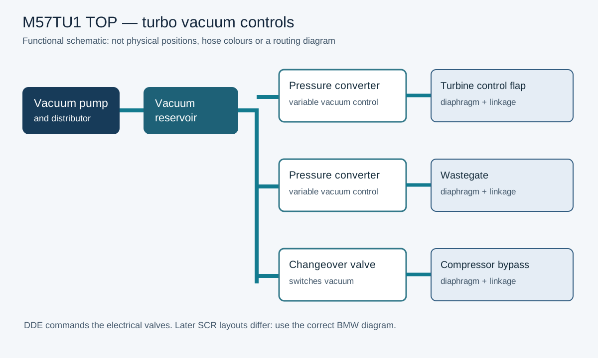
On the original M57TU1 TOP, the DDE controls three separate functions through vacuum-operated diaphragm actuators. A vacuum pump and reservoir supply electrically controlled valves. A pressure converter meters vacuum progressively; a changeover valve switches a vacuum circuit between its states. These electrical valves are not the same parts as the mechanical flaps they operate. The descriptions below follow BMW service training for the M57TU1 TOP; layouts and hose routing differ on later and market-specific engines.
| Control | Function | How it is operated | What to investigate |
|---|---|---|---|
| Turbine control flap | Progressively routes exhaust around the small high-pressure turbine towards the large low-pressure turbine. Closing the bypass favours small-stage response; opening it transfers more exhaust flow to the large stage. | Diaphragm actuator and proportional electropneumatic pressure converter. | Vacuum supply, converter output, actuator diaphragm, linkage and free movement of the flap. A fault can alter the changeover and low-speed response. |
| Compressor bypass flap | Bypasses the small compressor on the intake side when the large stage supplies the air at high flow. It is distinct from the exhaust-side turbine flap. | Diaphragm and electric vacuum changeover valve; the original TU1 TOP training describes the flap as open or closed. | Hose routing and sealing, changeover valve command and flap movement. A flap stuck in either position can disturb response or flow; a symptom alone cannot prove which position it is in. |
| Wastegate | Diverts some exhaust around the large low-pressure turbine to limit its drive, turbine speed and boost at high output. | Diaphragm and separate proportional electropneumatic pressure converter. | Converter, hoses, diaphragm and linkage; a stuck or incorrectly controlled gate can contribute to underboost or overboost. |
In BMW's original TU1 TOP full-load illustration, the small stage dominates below about 1,500 rpm, the turbine bypass opens progressively through the middle range, and the compressor bypass is open in the upper range. These are examples of full-load operation, not fixed switch points for every engine or partial-load condition. DDE maps, load and hysteresis affect operation.
Routing matters: BMW's early diagram shows a pump, distributor and reservoir supplying the controls. Its later M57T2 TOP SCR drawing shows separate supply paths for the wastegate and turbine-control converters, a changeover valve for the compressor bypass and heat protection near the turbo. Hoses can be incorrectly connected even when they look intact. Identify each endpoint using the correct VIN-specific diagram; do not assume colour or hose length proves routing on a repaired vehicle. Use heat-resistant hose and restore heat shields where specified. BMW M57T2 TOP SCR vacuum routing photographs and diagrams.
Diagnosing underboost, overboost and poor response
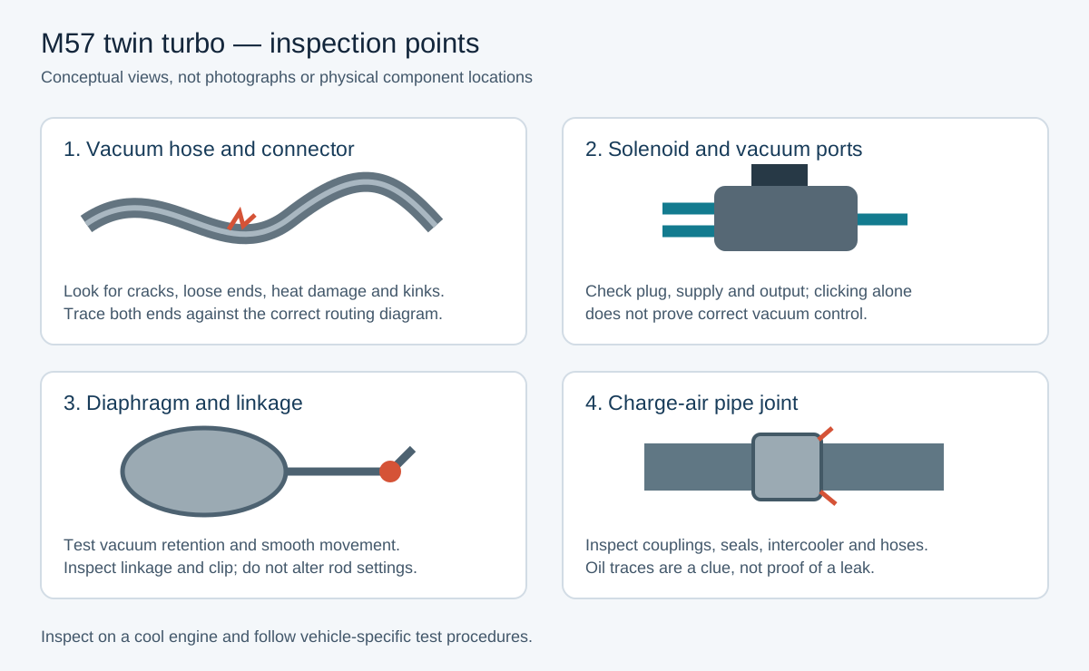
- Record the fault first. Identify the engine and emissions variant; save all DDE faults, freeze-frame conditions and recent repair history. Use BMW ISTA or a capable tool to read the full BMW code and description. Note whether the fault occurs at low speed, during the transition, or at high load; none identifies a failed turbo by itself.
- Inspect with the engine cool. Look for collapsed, split, heat-damaged or wrongly connected vacuum lines; damaged T-pieces, reservoir and electrical plugs; missing actuator clips; loose charge-air joints, intercooler damage and exhaust leaks upstream of the turbines. Oil mist around a charge joint can suggest a leak, but does not prove it. Follow the boost leak diagnostic guide.
- Check vacuum supply and retention. Using the correct test plan and gauge, check supply at the pump/distribution point, reservoir and relevant converter inlet. Isolate branches as directed to find a leak. The brake servo shares the vacuum system on some layouts: do not compromise braking or road-test with disconnected vacuum lines. Restore every connection before use.
- Test each diaphragm and linkage. Where the repair procedure permits, apply controlled vacuum with a hand pump directly to the identified actuator. It should move smoothly and hold vacuum to the specified test criteria; leakage suggests a diaphragm or connection fault, while poor travel with vacuum retained can indicate a sticking mechanism. Compare with the correct workshop procedure. Do not force the lever or adjust rod length or stops by eye; some disturbed actuators require a specified adjustment.
- Test the solenoid and control circuit. Reconnect the actuator, command the appropriate component through the diagnostic test plan and compare converter supply and output vacuum, movement and electrical command. Check connector condition, supply and wiring against the correct diagram. A clicking solenoid or moving rod alone does not prove correct modulation or airflow. Avoid applying battery voltage to unidentified pins.
- Compare requested and actual values. At key-on, engine-off, compare the manifold pressure reading with ambient pressure where the system permits; a large discrepancy merits sensor, wiring and reading-unit checks. Under safe, repeatable load, log requested and actual boost, engine speed, air mass and available control commands. Know whether the tool displays absolute pressure or gauge boost and whether the DDE has already reduced its target. A mismatch requires further testing, not an automatic turbo replacement.
- Check the rest of the air and exhaust path. Carry out a manufacturer-approved leak test of the charge system; do not exceed the specified test pressure. Check the filter, inlet restrictions, exhaust leaks and measured backpressure. EGR flow, air-mass readings, a restricted particulate filter or fuel faults can also change the result. Inspect turbocharger hardware when the preceding checks justify it.
- Verify the repair. Refit lines and shields correctly, run required adjustments or adaptations, clear faults only after recording them, and repeat the original test conditions. Check for returning codes and compare the new log with the original.
BMW's SI B12 10 09 for E70/E90 M57Y lists intake leaks, restricted inlet, actuator or vacuum faults, pressure sensor errors and exhaust backpressure as possible causes of boost deviations. It specifies the applicable turbo-control tests and a smoke test. Its warning about a particular air-mass test module applies to the software version discussed in that historical bulletin; use the current test plan for the vehicle.
Fault-code starting points
These examples are documented for the specified US M57Y vehicles; descriptions and generic OBD translations can vary with DDE software and scan tool. Read the complete description, status and conditions. A code identifies a monitored problem, not a guaranteed failed part.
| BMW DDE code | Documented meaning and first checks |
|---|---|
| 4521 | Charge-air pressure control deviation, pressure too high on E70/E90 M57Y. Check actual versus requested pressure, pressure sensing, wastegate and turbine flap control, vacuum routing and actuator movement. BMW SI B12 10 09. |
| 4530 | Charge-air pressure control deviation, pressure too low on E70/E90 M57Y. Check charge-air leaks, intake restriction, control vacuum and actuators, pressure sensing and exhaust backpressure. Boost-leak checks; BMW bulletin. |
| 480A / 481A | On M57Y, BMW lists particulate filter heavily loaded with high / above-maximum exhaust backpressure, respectively. Follow the DPF and sensor test plan and investigate why regeneration failed; do not assume the filter alone caused the fault. BMW SI B18 03 10; diesel particulate filters. |
| 3FF1 and 4595 / 459B / 4592 / 4596 / 4593 / 459C | BMW's E90 M57Y carbon-cleaning bulletin lists 3FF1 air-mass and these cylinder rough-running codes in a documented intake-carbon fault profile. They have other possible causes; confirm with the applicable tests and inspection. BMW SI B11 03 14, with intake photographs. |
Pictures and related diagnostic guides


- BMW M57T2 TOP SCR vacuum system — photographs and routing diagrams showing converters, pipes, reservoir and heat protection. This is a specified US 335d configuration, not a universal diagram.
- BMW M57Y intake-carbon service bulletin — photos of deposits and cleaning on an E90 335d.
- HELLA EGR valve photographs — comparison of a contaminated valve and a clean part; the pictured application is not an M57.
- Common EGR faults, carbon deposits and cleaning, common boost leaks and BMW diagnostics.
Engine and injection
The six-cylinder engine displaces 2,993 cc, with an 84 mm bore and 90 mm stroke, four valves per cylinder and common-rail direct injection. The later high-output M57 uses an aluminium crankcase with iron cylinder liners; the earlier 535d generation used an iron block. The later design combines a centrally placed injector and controlled intake air motion with a fast piezoelectric common-rail injection system. Injection can be divided into several events per combustion cycle, with rail pressure and quantity controlled to suit operating conditions. BMW describes the later engine as using third-generation common rail and piezo injectors. Exact injection pressure, injector type and components must be checked against the engine variant. BMW X6 specifications; BMW Advanced Diesel overview.
Emissions and market differences
Diesel oxidation catalysts reduce carbon monoxide and hydrocarbons; a diesel particulate filter traps soot and periodically burns it during regeneration. Exhaust-gas recirculation reduces combustion NOx by returning a controlled proportion of exhaust to the intake. Equipment varies by production date and market.
The US Advanced Diesel 335d and X5 xDrive35d also use selective catalytic reduction (SCR): a metered urea solution (AdBlue/diesel exhaust fluid) is mixed into the exhaust ahead of the SCR catalyst to reduce NOx. Sensors and control strategies monitor the system, and the fluid requires replenishment. Do not assume that every European M57 twin-turbo has the same SCR system. BMW US emissions description.
Performance upgrades: choose a complete package
The 200 kW early iron-block 535d and the 210 kW later aluminium-block M57TU2 TOP do not necessarily share turbo, fuel or installation parts. Identify the engine, DDE, original turbo and Bosch pump numbers and the vehicle's accessory layout first. Repair boost leaks, check vacuum control and measure fuel supply and engine health before tuning. The following are upgrade paths, not guaranteed outputs or universal safe limits.
| Approach | Hardware and trade-offs | Fuel and calibration |
|---|---|---|
| Factory turbos and recalibration | Retains the original two-stage response; a healthy intercooler, pipework and vacuum control are essential. The original compressors, turbine drive and air temperature eventually limit the useful increase. | A calibration must coordinate torque, fuel, air and boost with the actual engine and gearbox. Log rail pressure and intake temperature before assuming a pump upgrade is needed. |
| Hybrid low-pressure turbo | The larger turbo can receive a revised compressor, turbine, bearings and machined housings while retaining the two-stage arrangement and small turbo. Stage names vary by builder. More top-end flow can change spool and changeover behaviour. | Remap for the actual turbo and check charge cooling, exhaust backpressure, fuel and turbo speed. Ensure the small stage and bypass controls are healthy. |
| Matched hybrid pair | Both high- and low-pressure stages are upgraded as a matched system. Confirm original part numbers, actuator and vacuum hardware, oil supply and drain, pipework and core requirements. A “bolt-on” claim applies only to the vendor's specified configuration. | Airflow, pressure control, injection and transmission requests must be calibrated together; increased air capacity alone does not add the necessary fuel. |
| Large single-turbo conversion | Replaces the original staged layout with a different manifold and a selected turbo. It can offer higher flow but may sacrifice low-speed response. The specific build may need a manifold, mounting, oil and coolant plumbing where applicable, downpipe, intercooler pipes, actuator control and heat shielding. | A purpose-built calibration must address the changed boost control and diagnostics. Confirm bonnet, steering, brake and accessory clearance for the chassis; single-turbo parts for a 330d are not automatically a complete 335d conversion. |
Examples of available turbo upgrades
- Falcon M57TU2 335d hybrid: the supplier lists different low-pressure-stage street and racing specifications, with billet compressor and upgraded turbine/bearings. Its claimed 440 hp with R70 or 475 hp with R90 for the street version and 500+ hp for its racing version are supplier ratings with specified supporting changes, not measured guarantees or safe limits for every car.
- Tim's Turbos 335d low-pressure hybrid: this product uses a modified low-pressure core with revised K28 turbine, compressor and housing, and quotes a 500 hp rating. It is an example of a single-stage hybrid within the twin-turbo arrangement, not a complete large-single conversion.
- UK Turbo Performance GTB2871BB: the seller describes a large-frame turbo for single conversion on twin-turbo platforms and asks buyers to confirm configuration. Its 400 hp-plus target assumes supporting modifications and remapping; installation components and actual fit must be established for the vehicle.
Supplier power figures may use different measurement methods and supporting hardware; they do not establish crank-versus-wheel power, reliability, emissions compliance or interchangeability. Compare compressor and turbine details and request an itemised build, actuator setup, warranty and calibration plan.
Example hybrid and dual-pump builds
These are supplier ratings or reported builds, not universal stage definitions, guaranteed results or safe engine limits. Where a source does not specify wheel or crank measurement, the power basis remains unknown.
| Example | Hardware and supporting work | Claim and limits |
|---|---|---|
| Falcon Stage 2 K26-79, M57TU2 335d | Upgraded low-pressure-stage compressor, turbine and bearings; the supplier recommends an intercooler. Calibration must match the hardware. | Falcon rates it at 440 hp with R70 or 475 hp with R90. Measurement basis and complete supporting build are not established. This is a supplier rating, not proof either pump supports that output in every car. Falcon specifications. |
| Tim's Turbos Stage 3 low-pressure hybrid, 335d | Reworked low-pressure core with K28 turbine, modified compressor housing, bearings and balancing. The small turbo, bypass controls, cooling, fuelling and calibration must match. | The seller quotes a 500 hp turbo rating; this is not a measured complete-car result. Product description. |
| REVLOAD 500+ hp M57 guide | Suggested package: Turbosystems Stage 3 hybrid, Bosch 0 445 010 073 R90, specified injectors, larger intercooler and intake, rail sensor and pressure-control parts, valve springs and custom engine/transmission calibration. | The author reports 536 hp and 1,094.1 Nm on a similar setup, not a verified result for every listed part or for a dual-pump setup. Dyno method and wheel/crank basis are unstated. The guide lists exhaust modifications that require assessment for the intended use and local rules. REVLOAD build guide. |
| Santjer dual-CP3 US 335d kit | A belt-driven second CP3, dedicated metering controller, brackets, pulley drive and fuel connections; the vendor reports a dual-R70 setup with 100%-over injectors and offers R70/R90 combinations. | Santjer claims over 800 wheel hp for that described dual-R70 injector setup. This is a vendor-reported extreme combination, not a pump-only guarantee or recommendation for stock engine internals. Fitment is stated for the North American 335d. Santjer kit. |
A healthy standard system and calibration may be appropriate at lower targets. At greater load, match turbo maps, fuel delivery, intercooler, engine condition, gearbox and heat management to the intended use. None of the examples establishes a universal stock-bottom-end limit.
Aliant Auto’s E90 335d build
Aliant targets approximately 480 hp and 950 Nm from the 286 PS 335d. These are build objectives. The article provides no dyno trace verifying either figure.
The build pairs Turbosystems hybrid turbos with a Wagner EVO3 intercooler, revised intake, valve springs and 90 mm exhaust. Fuelling hardware includes a CP3 R90, DRV30 regulator and 2,700-bar rail sensor. Aliant lists xHP Stage 3 gearbox software and removal of EGR, DPF and VSA equipment. Aliant Auto’s E90 335d Stage 3 guide.
Sensor range and commanded rail pressure are different quantities. See the EDC16CP35 calibration notes for the two pressures quoted in the article.
Find the E90 335d map identifiers for torque demand, injection, rail pressure and two-stage boost control in the EDC16CP35 calibration map index.
Dual CP3 supporting design and checks
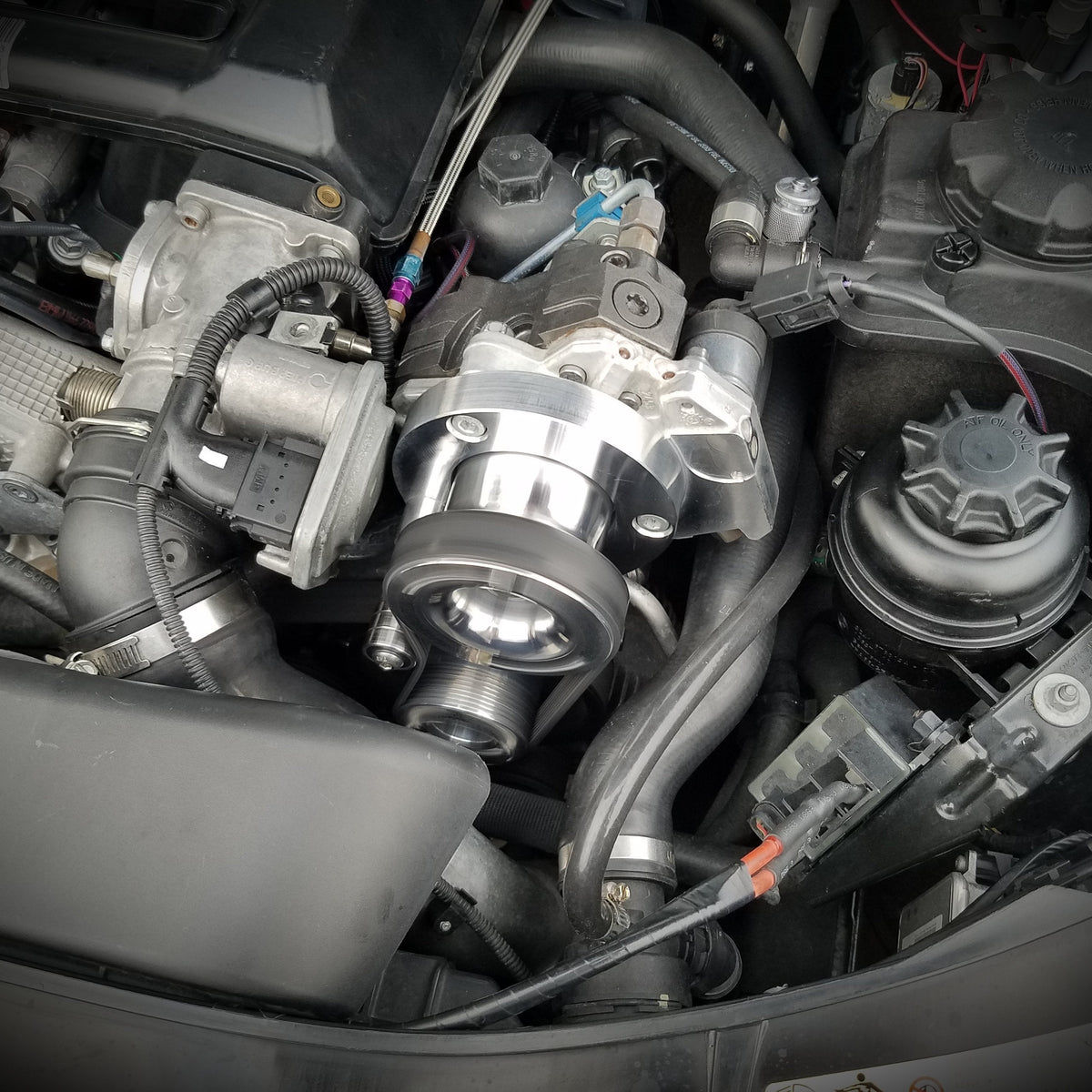
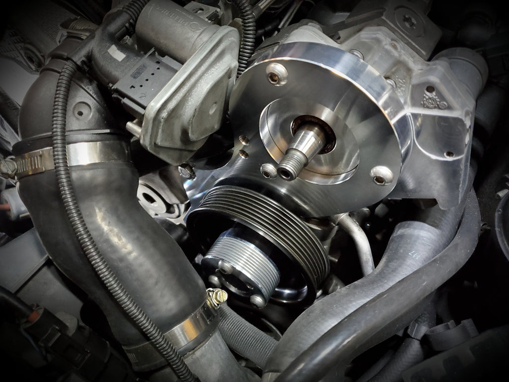
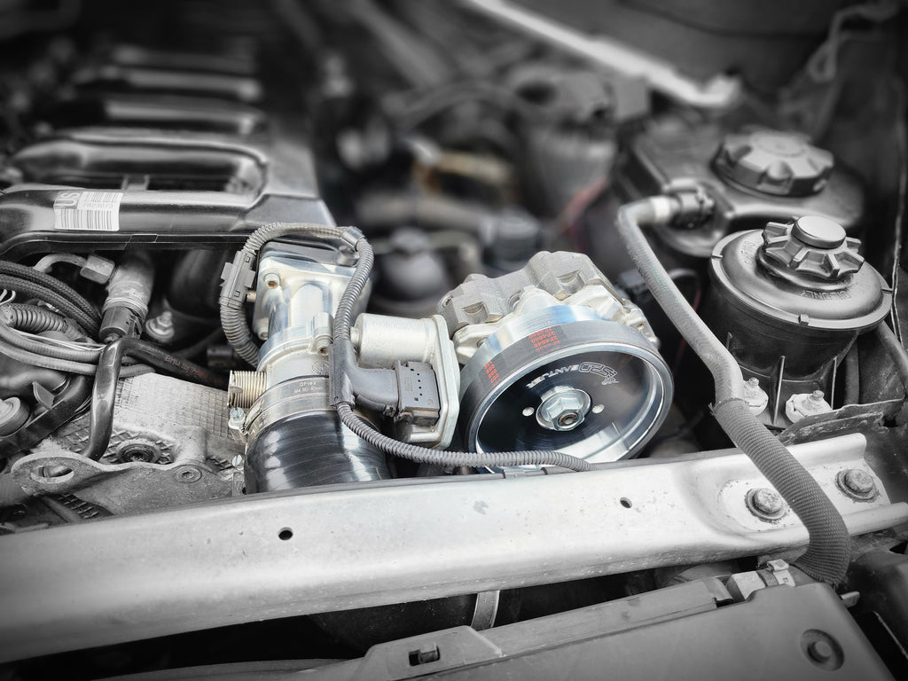
- Drive and clearance: identify the factory-driven and externally driven pump, check pulley ratio against permitted pump speed at maximum engine rpm, belt wrap and alignment, tensioner, brackets, accessory clearance and heat shielding.
- Low-pressure supply: size lift pump, filter, lines, fittings and return for both pumps. Measure inlet pressure under sustained load and check the electrical supply and controller current; an extra high-pressure pump cannot correct a starved feed.
- Metering and pressure control: verify the extra controller and metering valves work with the DDE, rail sensor and pressure regulator. Check idle stability and transient overshoot as well as requested versus actual rail pressure. Correctly scale any changed sensor; a higher-range sensor does not raise other components' pressure ratings.
- High-pressure connections: use specified pressure-rated lines, secure supports and approved fittings; control heat, vibration and contamination. Follow the exact vehicle or kit depressurisation, tightening and replacement procedures.
- Injectors and calibration: pump capacity increases potential rail supply; injector flow, injection duration, air mass and smoke limits still govern usable fuel. Use tested matched injectors and an engine- and transmission-specific calibration.
- Validation: establish a baseline and increase load progressively while logging requested and actual rail pressure, inlet supply, boost, charge temperature and exhaust temperature/backpressure where instrumented. Investigate unstable pressure or temperatures before further tuning.
See the Santjer US 335d and Whitbread 2009–11 US 335d kit descriptions for examples; their claims and fitments are specific to those products. The cited Santjer 335d kit excludes the X5 accessory layout. An Audi-donor pump requires specific drive, fitting and metering compatibility, not just the R90 label.
High-pressure fuel pumps, injectors and dual CP3
The pump must supply the requested mass at pressure throughout the pull. If rail pressure falls, first diagnose low-pressure feed, filter, control valves, electrical supply, injector return and actual versus requested rail pressure. A healthy pump upgrade increases available delivery, not necessarily the pressure rating of the rail, injector or sensor. Do not raise pressure beyond the ratings and calibration of the complete system.
- Replacement or larger single CP3: compare the installed Bosch part number with a compatible tested R70, R90 or specialist-modified pump. Confirm drive, metering valve, inlet/return, high-pressure port and pump-flow test conditions. See Bosch CP3 R70, CP3 R90 and other CP3 variants.
- Dual-pump conversion: typically adds a belt-driven pump, brackets, pulleys, belt, separate metering controller/harness, low-pressure supply and return connections and properly rated high-pressure lines and fittings. One pump continues to use the original drive; the external pump places load on its own belt drive. Pulley ratios, control, sensor scaling and pressure stability are part of the design.
- Fitment example: Santjer's 335d kit lists R70 and R90 options and states its fitment is verified for the North American 335d; that kit does not fit the X5 configuration with the specified alternator placement. Other kits can have different fitment; check chassis, engine, accessory positions and left/right-hand-drive clearance.
- Low-pressure supply: a larger or second high-pressure pump needs adequate clean inlet supply at the pump under load. Measure pressure and voltage at the operating point; a bigger in-tank pump may also require appropriate wiring and controller capacity. The Whitbread US 335d kit gives a setup-specific example and low-side upgrade options, not a universal power threshold.
- Injectors: larger or modified injectors can add delivery but change flow, spray and metering. Match the actual solenoid or piezo system, calibration and coding requirements; assess injection duration, rail stability, smoke and temperature rather than using injector percentage as a power promise.
CP4.2 high-pressure pump conversion
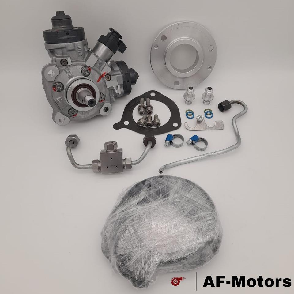
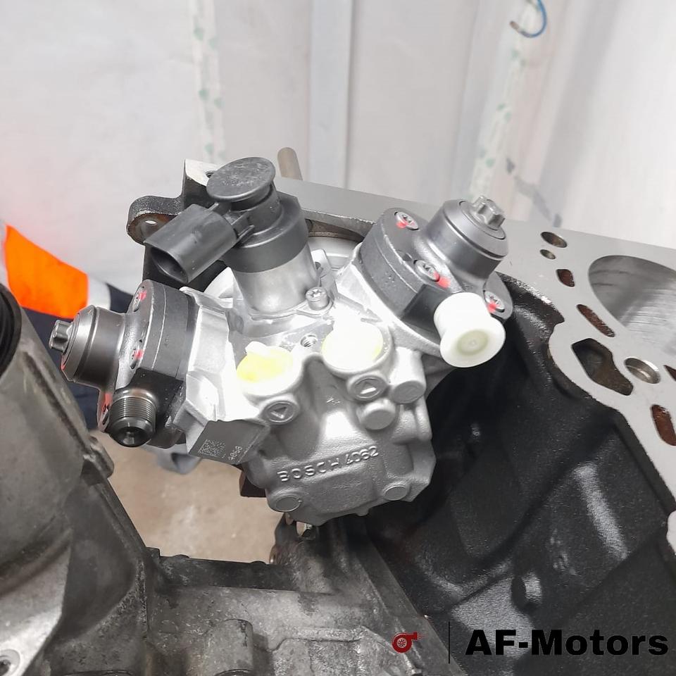
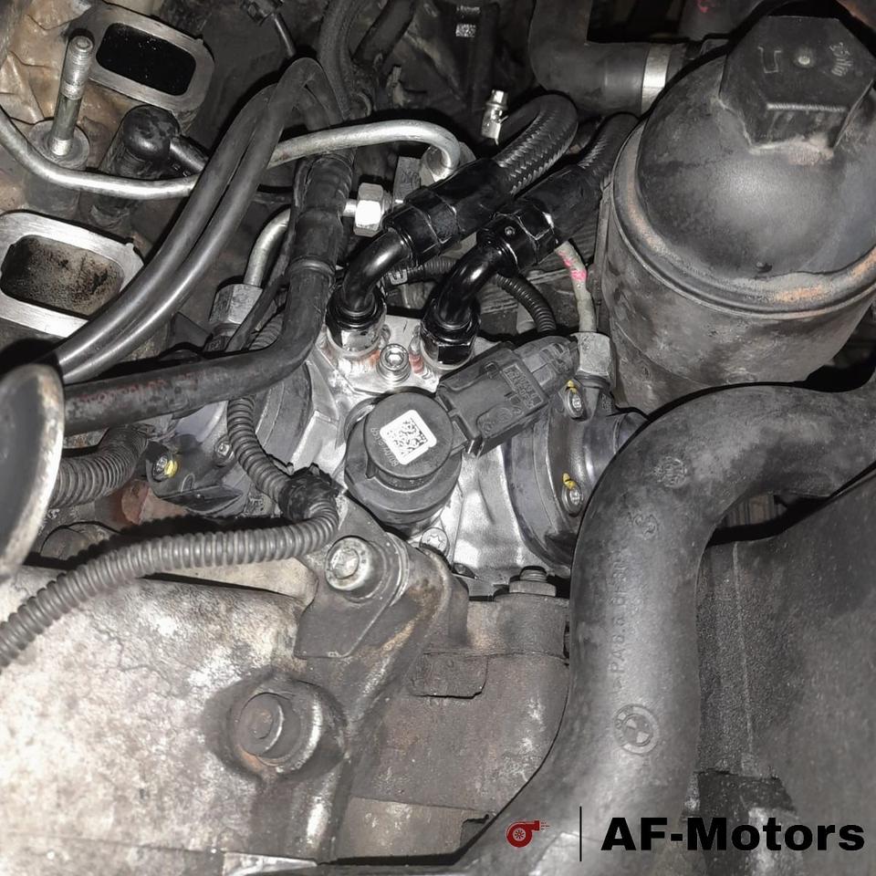
A single Bosch CP4.2 conversion is another aftermarket route used on M57 builds alongside larger single CP3 and dual-CP3 arrangements. It replaces the original high-pressure pump with an adapted CP4.2; it is not the same thing as adding a second CP3. CP4.2 has two pumping plungers, and BMW describes the CP4 family used on later engines as fuel-lubricated. BMW high-pressure pump technical information.
For example, AF-Motors offers an M57N/M57N2 CP4.2 kit with an adapted chain-drive pump, mounting adapter and low-pressure line adapters. The supplier describes either two high-pressure lines joining at the original rail through a T-piece or two lines feeding its two-inlet rail. It says some block modification is needed and a coolant pipe may need modification depending on the model. SAMMAPPING also lists an adapted CP4.2 for M57 335d/535d, with installation by that supplier. These are supplier-described conversions, not evidence that an unmodified donor CP4 fits every M57 or chassis.
- Mechanical fit: verify engine generation and block, mounting, chain drive and sprocket interface, rotation, pump speed, accessory and coolant-pipe clearance, and any machining against the specific kit instructions.
- Fuel circuit: check low-pressure supply and return, filtration and prime procedure, pressure-rated high-pressure lines, rail inlet arrangement, sensor and pressure-control parts. Do not infer the rail or injector pressure rating from the pump.
- Control and calibration: establish metering-valve electrical compatibility and the DDE control strategy; log requested and actual rail pressure across idle, transients and sustained load. Pump capacity does not establish injector capacity or an automatic power level.
- Condition and durability: use clean fuel of the specified grade and confirm the required inlet supply and priming. Pump wear or contamination can affect the rest of the fuel system. CP4 variants, fuels and duty cycles differ; neither a CP4 nor CP3 conversion is guaranteed failure-proof. See CP4 pump failures and diagnosis.
Common-rail systems retain very high pressure: use the specified depressurisation, clean-work and pressure-line replacement procedures. Compare a CP4.2 kit, a potential CP3 R110 adaptation and dual CP3 on documented fitment, measured flow at matching conditions and the needs of the complete build, rather than pump name alone.
Conversion photographs
- AF-Motors M57 CP4.2 conversion photographs — supplier listing with four photos showing its adapted pump and installation. The listing describes an M57N/M57N2 kit; it is a product demonstration, not an independently documented customer build.
- Santjer 335d dual-CP3 installation photographs — shows the belt-driven second pump and mounting arrangement on the supplier's North American 335d example. This is a CP3 setup, not CP4.
- Santjer X5 35d dual-CP3 photographs — a separate kit for the North American X5 layout, distinct from its 335d kit. Compare the accessory layout and verify fitment.
- RS Diagnostics M57 build profiles and photographs — includes a 135xd M57 biturbo and dual-CP3 project; follow the project profile for its specifications and results.
Photographs remain on their owners' sites; component placement, pipe routing and kit availability can differ. Image examples are not evidence that a conversion fits another car or that it has been independently tested for reliability.
Supporting modifications and verification
- Cooling and air: select intercooler core, pipework and couplings for flow, pressure drop, heat rejection and vehicle fit; compare intake temperatures on repeated pulls. Check radiator, oil cooling, crankcase ventilation and turbo oil feed and drain.
- Transmission and drivetrain: verify the fitted gearbox, torque converter, transfer box where fitted, differential and shafts. Torque management and transmission calibration need to match the hardware; avoid assuming every 6-speed or xDrive unit shares a limit.
- Engine durability: increased cylinder pressure, exhaust temperature and sustained load can expose worn bearings, head sealing, pistons, rods and valve gear. Inspect and build to the intended duty cycle rather than using a generic maximum horsepower number.
- Calibration and testing: establish a baseline, then log actual/requested boost and rail pressure, low-side supply, intake and coolant temperatures, injection quantities where supported, and exhaust temperature/backpressure with correctly placed instrumentation. Validate progressively under controlled load and stop if pressure control, temperatures or smoke indicate a problem.
- Retain applicable emissions equipment and ensure modifications suit the vehicle's use and local rules. High-pressure fuel systems require the specified depressurisation and clean installation procedures; never loosen a pressurised line.
Workshop and tuning considerations
- Identify the actual engine, emissions specification and hardware before diagnosing or calibrating. A 535d or xDrive35d badge covers more than one generation or market configuration.
- Low response or underboost can involve leaks in charge-air plumbing, intercooler or intake, exhaust leaks, turbo hardware, control valves or their actuation and vacuum supply where fitted. Test the complete system before condemning either turbo.
- Check requested and measured boost, air mass, actuator and valve operation, fault codes and relevant exhaust backpressure using procedures and limits for the specific vehicle. Compare under controlled, safe conditions.
- Excessive smoke, exhaust temperature, overspeed or boost can damage components. Calibration changes should respect the actual turbo, fuel system, transmission and emissions hardware; do not treat a generic boost or power number as a safe limit.
- Blocked DPFs and EGR, air-metering or injection faults can affect boost and drivability. Diagnose the cause and retain applicable emissions equipment.
R110 donor pumps
Some larger CP3 variants are considered for high-output conversions. The CP3 R110 guide identifies documented Volvo and Hyundai donor examples and distinguishes Audi L110 pumps. These references do not verify a direct-fit R110 conversion on the M57. Check pump shaft, drive, rotation, mounting, metering, supply and line compatibility for the specific kit and engine, and compare bench flow at the relevant pressure and pump speed before choosing one.
For the distinction between the early 272 PS 535d solenoid injectors and later M57TU2 TOP piezo injectors, along with 2.5/3.0 M57 and lower-output examples, see BMW M57 injector types: solenoid and piezo.
For a photographed twin-turbo M57 trial fit in a Volkswagen LT28 Sven Hedin, see Range Rover and Volkswagen camper conversions.
For the 210 kW E90 335d with EDC16CP35, see BMW M57 ASMod and air mass diagnosis.