The high-output 3.0-litre M57 uses BMW's Variable Twin Turbo (VTT), a regulated two-stage system with differently sized turbochargers. This guide covers the M57-based 535d, 335d, X5 3.0sd/xDrive35d and X6 xDrive35d. Model badges alone do not identify an engine: later vehicles and different markets can use other diesel engines and emissions systems. Check the VIN, build date and engine identification before ordering parts or applying specifications. See the M57 engine family.
Applications and output
| Application | Representative factory rating | Notes |
|---|---|---|
| E60/E61 535d, original M57D30TÜ TOP | 200 kW (272 PS; 268 bhp) at 4,400 rpm; 560 Nm at 2,000 rpm | First 535d VTT generation, introduced in 2004. |
| Later E60/E61 535d, M57D30TÜ2 TOP | 210 kW (286 PS; 282 bhp); 580 Nm | Updated aluminium-block engine; market and production date matter. |
| E90/E91/E92 335d | 210 kW (286 PS; 282 bhp); 580 Nm | European specification; the US 335d had a different rating and emissions configuration. |
| E70 X5 3.0sd / xDrive35d | 210 kW (286 PS; 282 bhp); 580 Nm | European 3.0sd launch rating; later naming and market specifications differ. |
| E71 X6 xDrive35d | 210 kW (286 PS; 282 bhp) at 4,400 rpm; 580 Nm at 1,750–2,250 rpm | The launch model used the M57-based two-stage diesel. BMW used xDrive35d for the X6; verify the actual vehicle rather than assuming a 3.0sd badge. |
BMW specified the US-market 335d and X5 xDrive35d at 265 hp at 4,200 rpm and 425 lb-ft at 1,750–2,250 rpm. These ratings should not be interchanged with the European figures. Sources: BMW 535d launch, updated 5 Series, 335d launch, X5 3.0sd, X6 launch specifications and US Advanced Diesel.
How the two-stage turbo system works
Two differently sized turbochargers cooperate across the operating range. The small high-pressure unit has low rotational inertia and responds quickly at low exhaust flow; the large low-pressure unit can move more air at higher flow. Their operation is managed progressively by the engine control unit according to operating conditions, rather than switching at one fixed engine speed.
- Low speed and load: exhaust energy is directed principally through the small turbine for quick response. The small compressor provides the main pressure rise.
- Transition and mid-range: the large compressor pre-compresses the incoming air and the small compressor raises its pressure further. Exhaust flow is progressively distributed between the turbines.
- High flow: the large turbo becomes the main charger. Bypass passages reduce restriction around the small stage; the small unit is effectively on standby.
The system includes a turbine control/bypass, a compressor bypass and a wastegate. The turbine control directs exhaust energy between stages; the compressor bypass provides a route around the small compressor when appropriate; the wastegate limits turbine drive and boost. Charge air passes through an intercooler before reaching the engine. The valves are regulated, so a pressure figure or valve position at one load is not a universal setting. BMW's history of the system and its US technical overview describe the staged operation.
Turbo control valves and vacuum supply
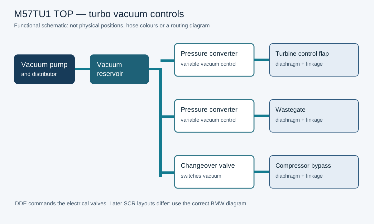
On the original M57TU1 TOP, the DDE controls three separate functions through vacuum-operated diaphragm actuators. A vacuum pump and reservoir supply electrically controlled valves. A pressure converter meters vacuum progressively; a changeover valve switches a vacuum circuit between its states. These electrical valves are not the same parts as the mechanical flaps they operate. The descriptions below follow BMW service training for the M57TU1 TOP; layouts and hose routing differ on later and market-specific engines.
| Control | Function | How it is operated | What to investigate |
|---|---|---|---|
| Turbine control flap | Progressively routes exhaust around the small high-pressure turbine towards the large low-pressure turbine. Closing the bypass favours small-stage response; opening it transfers more exhaust flow to the large stage. | Diaphragm actuator and proportional electropneumatic pressure converter. | Vacuum supply, converter output, actuator diaphragm, linkage and free movement of the flap. A fault can alter the changeover and low-speed response. |
| Compressor bypass flap | Bypasses the small compressor on the intake side when the large stage supplies the air at high flow. It is distinct from the exhaust-side turbine flap. | Diaphragm and electric vacuum changeover valve; the original TU1 TOP training describes the flap as open or closed. | Hose routing and sealing, changeover valve command and flap movement. A flap stuck in either position can disturb response or flow; a symptom alone cannot prove which position it is in. |
| Wastegate | Diverts some exhaust around the large low-pressure turbine to limit its drive, turbine speed and boost at high output. | Diaphragm and separate proportional electropneumatic pressure converter. | Converter, hoses, diaphragm and linkage; a stuck or incorrectly controlled gate can contribute to underboost or overboost. |
In BMW's original TU1 TOP full-load illustration, the small stage dominates below about 1,500 rpm, the turbine bypass opens progressively through the middle range, and the compressor bypass is open in the upper range. These are examples of full-load operation, not fixed switch points for every engine or partial-load condition. DDE maps, load and hysteresis affect operation.
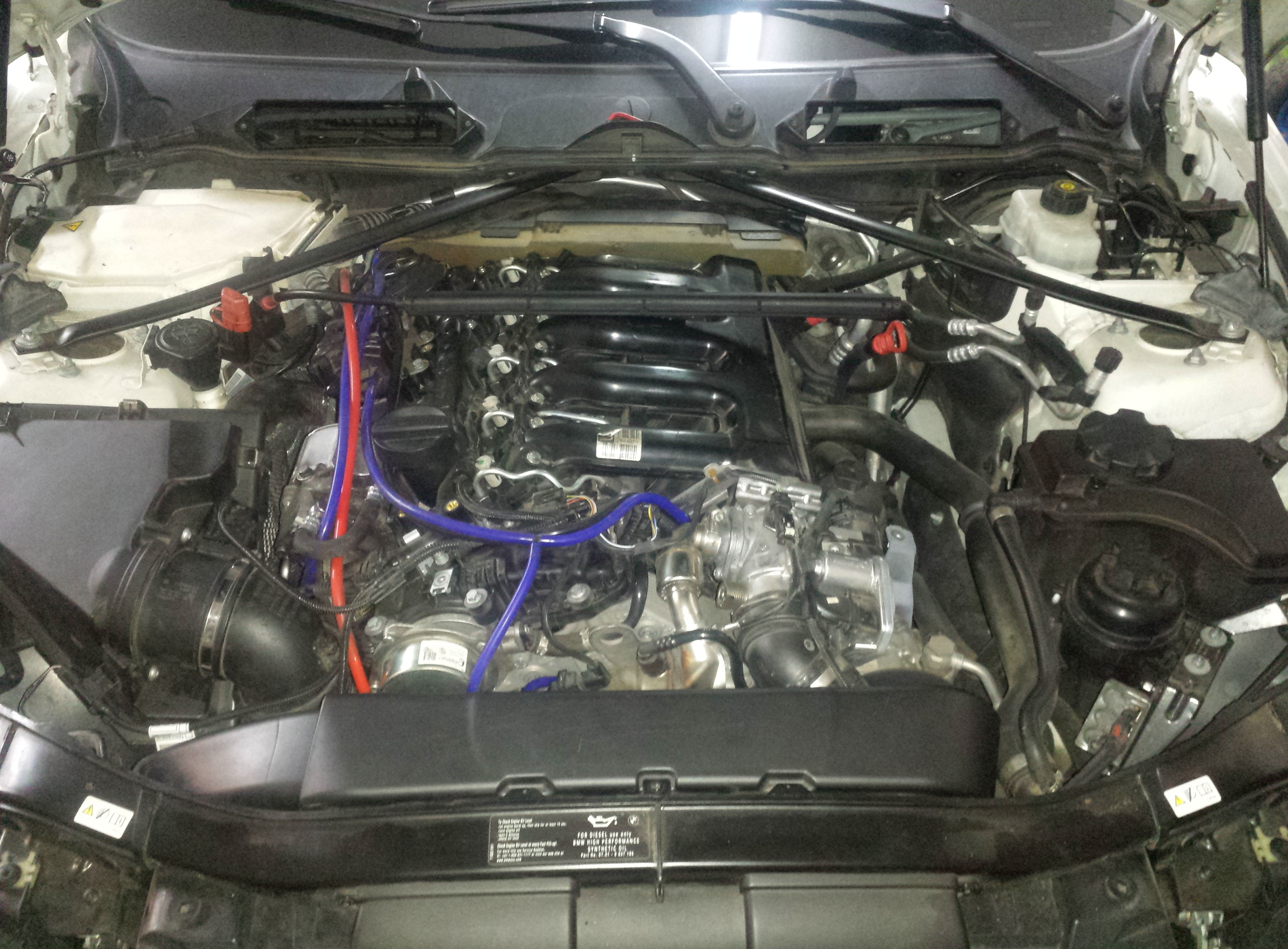
Routing matters: BMW's early diagram shows a pump, distributor and reservoir supplying the controls. Its later M57T2 TOP SCR drawing shows separate supply paths for the wastegate and turbine-control converters, a changeover valve for the compressor bypass and heat protection near the turbo. Hoses can be incorrectly connected even when they look intact. Identify each endpoint using the correct VIN-specific diagram; do not assume colour or hose length proves routing on a repaired vehicle. Use heat-resistant hose and restore heat shields where specified. BMW M57T2 TOP SCR vacuum routing photographs and diagrams.
Diagnosing underboost, overboost and poor response
- Record the fault first. Identify the engine and emissions variant; save all DDE faults, freeze-frame conditions and recent repair history. Use BMW ISTA or a capable tool to read the full BMW code and description. Note whether the fault occurs at low speed, during the transition, or at high load; none identifies a failed turbo by itself.
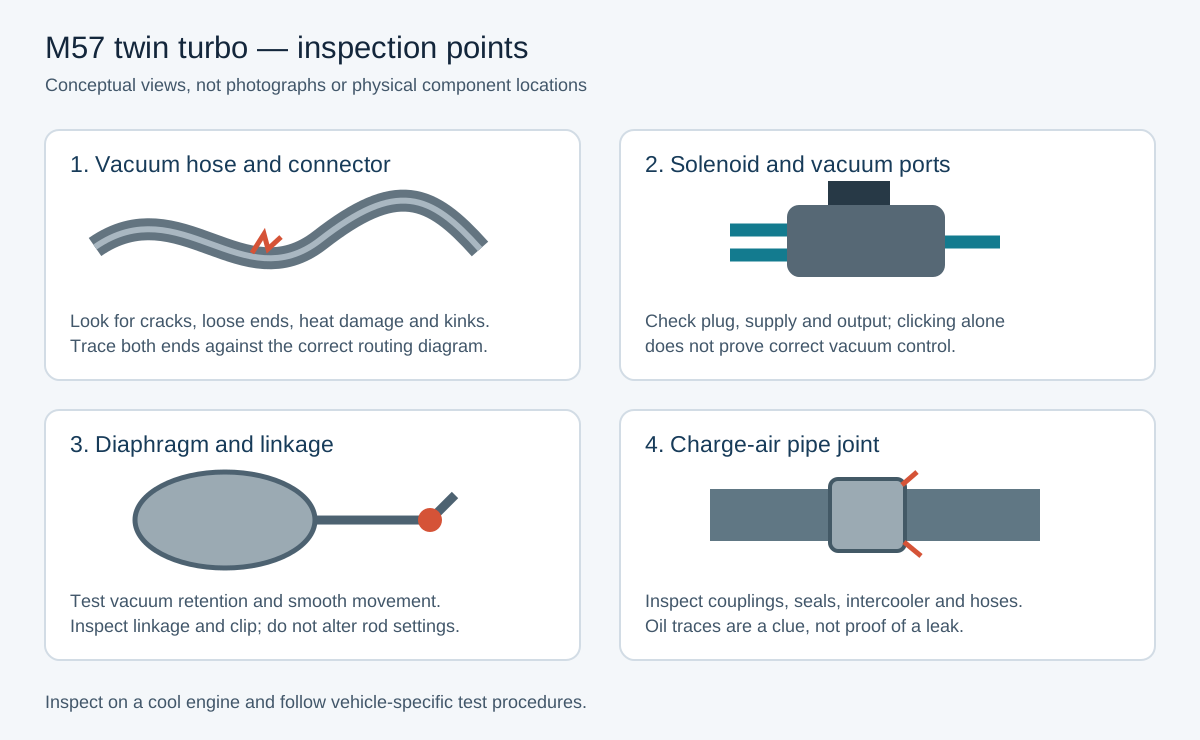
- Inspect with the engine cool. Look for collapsed, split, heat-damaged or wrongly connected vacuum lines; damaged T-pieces, reservoir and electrical plugs; missing actuator clips; loose charge-air joints, intercooler damage and exhaust leaks upstream of the turbines. Oil mist around a charge joint can suggest a leak, but does not prove it. Follow the boost leak diagnostic guide.
- Check vacuum supply and retention. Using the correct test plan and gauge, check supply at the pump/distribution point, reservoir and relevant converter inlet. Isolate branches as directed to find a leak. The brake servo shares the vacuum system on some layouts: do not compromise braking or road-test with disconnected vacuum lines. Restore every connection before use.
- Test each diaphragm and linkage. Where the repair procedure permits, apply controlled vacuum with a hand pump directly to the identified actuator. It should move smoothly and hold vacuum to the specified test criteria; leakage suggests a diaphragm or connection fault, while poor travel with vacuum retained can indicate a sticking mechanism. Compare with the correct workshop procedure. Do not force the lever or adjust rod length or stops by eye; some disturbed actuators require a specified adjustment.
- Test the solenoid and control circuit. Reconnect the actuator, command the appropriate component through the diagnostic test plan and compare converter supply and output vacuum, movement and electrical command. Check connector condition, supply and wiring against the correct diagram. A clicking solenoid or moving rod alone does not prove correct modulation or airflow. Avoid applying battery voltage to unidentified pins.
- Compare requested and actual values. At key-on, engine-off, compare the manifold pressure reading with ambient pressure where the system permits; a large discrepancy merits sensor, wiring and reading-unit checks. Under safe, repeatable load, log requested and actual boost, engine speed, air mass and available control commands. Know whether the tool displays absolute pressure or gauge boost and whether the DDE has already reduced its target. A mismatch requires further testing, not an automatic turbo replacement.
- Check the rest of the air and exhaust path. Carry out a manufacturer-approved leak test of the charge system; do not exceed the specified test pressure. Check the filter, inlet restrictions, exhaust leaks and measured backpressure. EGR flow, air-mass readings, a restricted particulate filter or fuel faults can also change the result. Inspect turbocharger hardware when the preceding checks justify it.
- Verify the repair. Refit lines and shields correctly, run required adjustments or adaptations, clear faults only after recording them, and repeat the original test conditions. Check for returning codes and compare the new log with the original.
BMW's SI B12 10 09 for E70/E90 M57Y lists intake leaks, restricted inlet, actuator or vacuum faults, pressure sensor errors and exhaust backpressure as possible causes of boost deviations. It specifies the applicable turbo-control tests and a smoke test. Its warning about a particular air-mass test module applies to the software version discussed in that historical bulletin; use the current test plan for the vehicle.
Fault-code starting points
These examples are documented for the specified US M57Y vehicles; descriptions and generic OBD translations can vary with DDE software and scan tool. Read the complete description, status and conditions. A code identifies a monitored problem, not a guaranteed failed part.
| BMW DDE code | Documented meaning and first checks |
|---|---|
| 4521 | Charge-air pressure control deviation, pressure too high on E70/E90 M57Y. Check actual versus requested pressure, pressure sensing, wastegate and turbine flap control, vacuum routing and actuator movement. BMW SI B12 10 09. |
| 4530 | Charge-air pressure control deviation, pressure too low on E70/E90 M57Y. Check charge-air leaks, intake restriction, control vacuum and actuators, pressure sensing and exhaust backpressure. Boost-leak checks; BMW bulletin. |
| 480A / 481A | On M57Y, BMW lists particulate filter heavily loaded with high / above-maximum exhaust backpressure, respectively. Follow the DPF and sensor test plan and investigate why regeneration failed; do not assume the filter alone caused the fault. BMW SI B18 03 10; diesel particulate filters. |
| 3FF1 and 4595 / 459B / 4592 / 4596 / 4593 / 459C | BMW's E90 M57Y carbon-cleaning bulletin lists 3FF1 air-mass and these cylinder rough-running codes in a documented intake-carbon fault profile. They have other possible causes; confirm with the applicable tests and inspection. BMW SI B11 03 14, with intake photographs. |
Pictures and related diagnostic guides


- BMW M57T2 TOP SCR vacuum system — photographs and routing diagrams showing converters, pipes, reservoir and heat protection. This is a specified US 335d configuration, not a universal diagram.
- BMW M57Y intake-carbon service bulletin — photos of deposits and cleaning on an E90 335d.
- HELLA EGR valve photographs — comparison of a contaminated valve and a clean part; the pictured application is not an M57.
- Common EGR faults, carbon deposits and cleaning, common boost leaks and BMW diagnostics.
Engine and injection
The six-cylinder engine displaces 2,993 cc, with an 84 mm bore and 90 mm stroke, four valves per cylinder and common-rail direct injection. The later high-output M57 uses an aluminium crankcase with iron cylinder liners; the earlier 535d generation used an iron block. The later design combines a centrally placed injector and controlled intake air motion with a fast piezoelectric common-rail injection system. Injection can be divided into several events per combustion cycle, with rail pressure and quantity controlled to suit operating conditions. BMW describes the later engine as using third-generation common rail and piezo injectors. Exact injection pressure, injector type and components must be checked against the engine variant. BMW X6 specifications; BMW Advanced Diesel overview.
Emissions and market differences
Diesel oxidation catalysts reduce carbon monoxide and hydrocarbons; a diesel particulate filter traps soot and periodically burns it during regeneration. Exhaust-gas recirculation reduces combustion NOx by returning a controlled proportion of exhaust to the intake. Equipment varies by production date and market.
The US Advanced Diesel 335d and X5 xDrive35d also use selective catalytic reduction (SCR): a metered urea solution (AdBlue/diesel exhaust fluid) is mixed into the exhaust ahead of the SCR catalyst to reduce NOx. Sensors and control strategies monitor the system, and the fluid requires replenishment. Do not assume that every European M57 twin-turbo has the same SCR system. BMW US emissions description.
Workshop and tuning considerations
- Identify the actual engine, emissions specification and hardware before diagnosing or calibrating. A 535d or xDrive35d badge covers more than one generation or market configuration.
- Low response or underboost can involve leaks in charge-air plumbing, intercooler or intake, exhaust leaks, turbo hardware, control valves or their actuation and vacuum supply where fitted. Test the complete system before condemning either turbo.
- Check requested and measured boost, air mass, actuator and valve operation, fault codes and relevant exhaust backpressure using procedures and limits for the specific vehicle. Compare under controlled, safe conditions.
- Excessive smoke, exhaust temperature, overspeed or boost can damage components. Calibration changes should respect the actual turbo, fuel system, transmission and emissions hardware; do not treat a generic boost or power number as a safe limit.
- Blocked DPFs and EGR, air-metering or injection faults can affect boost and drivability. Diagnose the cause and retain applicable emissions equipment.