Tuning Wiki

This is a historical revision. Read the current page or return to its history.

Page organisation in this revision
Page type
Technical article
Subject
Carburettors
Parent
Section level
Applies to
No ECU-specific applicability
Tool groups
None
Manufacturers
None

Changes from revision 6 to revision 7

Removed text is struck through; added text is highlighted.

The Weber IDA family exists in two distinct high-flow downdraft configurations: the famous two-barrel 48 IDA (classic air-cooled VW drag/Cal-Look builds and V8 racing manifolds such as the Ford GT40 and AC Cobra) and the three-barrel 40 / 46 IDA 3C (early Porsche 911 and 904 GTS flat-sixes). Unlike DCOE and IDF carburettors, IDA floats sit inside the main body rather than hanging from the top cover.

Weber 48 IDA two-barrel downdraft carburettor. Photo: Reforma.imufomot, Wikimedia Commons, Public domain.

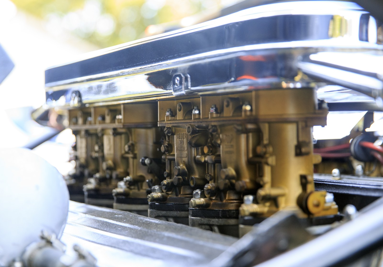
Two triple-barrel Weber downdraft carburettors on a Lamborghini Miura P400 S V12. The photographer identifies these as 40 IDL 3L, a different model from the IDA 3C. Photo: Mr.choppers, Wikimedia Commons, CC BY-SA 3.0.

Adjustment screw diagrams

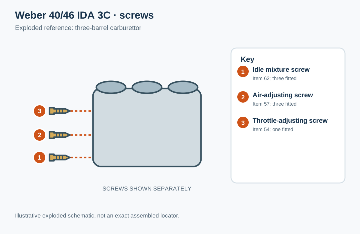
Weber 40/46 IDA 3C and 3C1: idle mixture screw 62, air-adjusting screw 57 and throttle-adjusting screw 54. Original schematic for Tuning Wiki, CC BY 4.0, based on the Weber parts drawing and key. Screws are shown separately to identify the parts, not their exact assembled locations.

Weber 48 IDA: idle mixture screws low on the fuel-bowl side. Original simplified redraw for Tuning Wiki, CC BY 4.0; based on Reforma.imufomot’s public-domain photograph and Carburetion.com’s 48 IDA parts key, item 20. The 40/46 IDA 3C layout differs; not to scale.

48 IDA exploded diagram and parts key, Carburetion.com: idle mixture screw 20 and throttle stop screw 39.Weber 40/46 IDA 3C and 3C1 exploded diagram and parts list (PDF hosted by Racetep): throttle adjusting screw 54, air adjusting screw 57 and idle mixture adjusting screw 62.

These keys are for their respective drawings. The two-barrel 48 IDA and three-barrel IDA 3C layouts are different; match the model before locating a screw.

1. Models & factory baseline jetting

ModelBarrelsFactory choke / auxMain jetEmulsion tubeAir correctorIdle jetPump / bleed 48 IDA (19030.015)2-barrel37 mm / 4.5135F712070F1050 / 000 (2.00 needle) 40 IDA 3C / 3C13-barrel28–30 mm / 4.5125F261805550 / 000 (1.75 needle) 46 IDA 3C / 3C13-barrel40 mm / 4.5170F241457050 / 100 (1.75 needle)

2. Body-retained float adjustment (unique to IDA)

Because the IDA float remains inside the main carburettor body when the top cover is removed, float level cannot be measured off the lid (Weber FL1007 IDA Float Instructions; Weber Performance Float Guide):

Tools required: needle-and-seat gauge (98014.200) and spring retainer (98013.800) to hold the float lightly against the needle ball without compressing it. 48 IDA (2-barrel): set needle-and-seat gauge dimension to 24 mm (24.2 mm), then verify the top of the float protrudes 5.5–6.0 mm above the top face of the main body. 40 / 46 IDA 3C (3-barrel): set needle-and-seat gauge dimension to 18 mm, then verify float height measures 12.5–13.0 mm from the top face of the main body. Fuel pressure: many 48 IDA installations run around 3.5–4.0 psi constant regulated pressure, ensuring float needles shut off cleanly without aeration.

3. IDA tuning characteristics

Bleedless F10 idle jets (48 IDA): as Webcon UK notes, the 48 IDA uses the F10 idle jet series which has no side air bleed, relying instead on the idle jet orifice and progression-hole geometry near the butterfly. Progression-hole variations: early competition 48 IDA units often have only two progression holes, giving abrupt race-oriented transition; adding a third progression hole (a common street modification) or tailoring choke size smooths low-RPM transition on street-driven V8s and flat-fours (GT40 48 IDA tuning notes). Emulsion tube selection (F7, F11, F2, F4): remember that Weber F-numbers are arbitrary part labels, not sequential richness steps. Smaller outer-diameter tubes leave a larger fuel "reserve curtain" in the well for high-demand engines, while hole placement at the top, waist or bottom shifts main-circuit cut-in and high-RPM air correction. F7 brings the main circuit in early and strongly; if mid-range transition runs overly rich before the idle circuit signs off, a tube with higher upper drillings delays main-circuit pickup. Choke sizing on V8s: starting with slightly smaller venturis helps dial in progression and signal on aggressive-cam V8s before stepping up choke diameter until peak power stops improving.

4. Related pages

Weber carburettor tuning overview Weber IDF carburettors: specs and tuning Weber DCOE and DCO-SP carburettors: specs and tuning Carburettor fuel circuits and metering

Sources

Weber 46/48 IDA and 40/46 IDA 3C Float Level Instructions (FL1007) and Weber Performance Float Adjustment Guide. Baseline Weber Jetting Chart and Weber Factory Jetting Chart. Webcon UK: DCOE & 48 IDA Idle Jet Note (F10).

Page organisation changed

FieldRevision 6Revision 7
Page typeTechnical articleTechnical article
SubjectCarburettorsCarb Tuning
ParentSection levelSection level
Applies toNo ECU-specific applicabilityNo ECU-specific applicability
Tool groupsNoneNone
Vehicle makesNoneNone

Rendered revisions

Open each version to inspect formatting, tables and photographs.

Revision 6: Weber IDA and IDA 3C carburettors: specs and tuning

The Weber IDA family exists in two distinct high-flow downdraft configurations: the famous two-barrel 48 IDA (classic air-cooled VW drag/Cal-Look builds and V8 racing manifolds such as the Ford GT40 and AC Cobra) and the three-barrel 40 / 46 IDA 3C (early Porsche 911 and 904 GTS flat-sixes). Unlike DCOE and IDF carburettors, IDA floats sit inside the main body rather than hanging from the top cover.
Weber 48 IDA two-barrel downdraft carburettor
Weber 48 IDA two-barrel downdraft carburettor. Photo: Reforma.imufomot, Wikimedia Commons, Public domain.
Two triple-barrel Weber carburettors on a Lamborghini Miura V12
Two triple-barrel Weber downdraft carburettors on a Lamborghini Miura P400 S V12. The photographer identifies these as 40 IDL 3L, a different model from the IDA 3C. Photo: Mr.choppers, Wikimedia Commons, CC BY-SA 3.0.

Adjustment screw diagrams

Simplified exploded screw reference for Weber 40 and 46 IDA 3C and 3C1
Weber 40/46 IDA 3C and 3C1: idle mixture screw 62, air-adjusting screw 57 and throttle-adjusting screw 54. Original schematic for Tuning Wiki, CC BY 4.0, based on the Weber parts drawing and key. Screws are shown separately to identify the parts, not their exact assembled locations.
Simplified Weber 48 IDA diagram showing idle mixture screws on the fuel bowl side
Weber 48 IDA: idle mixture screws low on the fuel-bowl side. Original simplified redraw for Tuning Wiki, CC BY 4.0; based on Reforma.imufomot’s public-domain photograph and Carburetion.com’s 48 IDA parts key, item 20. The 40/46 IDA 3C layout differs; not to scale.

These keys are for their respective drawings. The two-barrel 48 IDA and three-barrel IDA 3C layouts are different; match the model before locating a screw.

1. Models & factory baseline jetting

ModelBarrelsFactory choke / auxMain jetEmulsion tubeAir correctorIdle jetPump / bleed
48 IDA (19030.015)2-barrel37 mm / 4.5135F712070F1050 / 000 (2.00 needle)
40 IDA 3C / 3C13-barrel28–30 mm / 4.5125F261805550 / 000 (1.75 needle)
46 IDA 3C / 3C13-barrel40 mm / 4.5170F241457050 / 100 (1.75 needle)

2. Body-retained float adjustment (unique to IDA)

Because the IDA float remains inside the main carburettor body when the top cover is removed, float level cannot be measured off the lid (Weber FL1007 IDA Float Instructions; Weber Performance Float Guide):

  • Tools required: needle-and-seat gauge (98014.200) and spring retainer (98013.800) to hold the float lightly against the needle ball without compressing it.
  • 48 IDA (2-barrel): set needle-and-seat gauge dimension to 24 mm (24.2 mm), then verify the top of the float protrudes 5.5–6.0 mm above the top face of the main body.
  • 40 / 46 IDA 3C (3-barrel): set needle-and-seat gauge dimension to 18 mm, then verify float height measures 12.5–13.0 mm from the top face of the main body.
  • Fuel pressure: many 48 IDA installations run around 3.5–4.0 psi constant regulated pressure, ensuring float needles shut off cleanly without aeration.

3. IDA tuning characteristics

  • Bleedless F10 idle jets (48 IDA): as Webcon UK notes, the 48 IDA uses the F10 idle jet series which has no side air bleed, relying instead on the idle jet orifice and progression-hole geometry near the butterfly.
  • Progression-hole variations: early competition 48 IDA units often have only two progression holes, giving abrupt race-oriented transition; adding a third progression hole (a common street modification) or tailoring choke size smooths low-RPM transition on street-driven V8s and flat-fours (GT40 48 IDA tuning notes).
  • Emulsion tube selection (F7, F11, F2, F4): remember that Weber F-numbers are arbitrary part labels, not sequential richness steps. Smaller outer-diameter tubes leave a larger fuel "reserve curtain" in the well for high-demand engines, while hole placement at the top, waist or bottom shifts main-circuit cut-in and high-RPM air correction. F7 brings the main circuit in early and strongly; if mid-range transition runs overly rich before the idle circuit signs off, a tube with higher upper drillings delays main-circuit pickup.
  • Choke sizing on V8s: starting with slightly smaller venturis helps dial in progression and signal on aggressive-cam V8s before stepping up choke diameter until peak power stops improving.

4. Related pages

Sources

Revision 7: Weber IDA and IDA 3C carburettors: specs and tuning

The Weber IDA family exists in two distinct high-flow downdraft configurations: the famous two-barrel 48 IDA (classic air-cooled VW drag/Cal-Look builds and V8 racing manifolds such as the Ford GT40 and AC Cobra) and the three-barrel 40 / 46 IDA 3C (early Porsche 911 and 904 GTS flat-sixes). Unlike DCOE and IDF carburettors, IDA floats sit inside the main body rather than hanging from the top cover.

Weber 48 IDA two-barrel downdraft carburettor
Weber 48 IDA two-barrel downdraft carburettor. Photo: Reforma.imufomot, Wikimedia Commons, Public domain.
Two triple-barrel Weber carburettors on a Lamborghini Miura V12
Two triple-barrel Weber downdraft carburettors on a Lamborghini Miura P400 S V12. The photographer identifies these as 40 IDL 3L, a different model from the IDA 3C. Photo: Mr.choppers, Wikimedia Commons, CC BY-SA 3.0.

Adjustment screw diagrams

Simplified exploded screw reference for Weber 40 and 46 IDA 3C and 3C1
Weber 40/46 IDA 3C and 3C1: idle mixture screw 62, air-adjusting screw 57 and throttle-adjusting screw 54. Original schematic for Tuning Wiki, CC BY 4.0, based on the Weber parts drawing and key. Screws are shown separately to identify the parts, not their exact assembled locations.
Simplified Weber 48 IDA diagram showing idle mixture screws on the fuel bowl side
Weber 48 IDA: idle mixture screws low on the fuel-bowl side. Original simplified redraw for Tuning Wiki, CC BY 4.0; based on Reforma.imufomot’s public-domain photograph and Carburetion.com’s 48 IDA parts key, item 20. The 40/46 IDA 3C layout differs; not to scale.

These keys are for their respective drawings. The two-barrel 48 IDA and three-barrel IDA 3C layouts are different; match the model before locating a screw.

1. Models & factory baseline jetting

ModelBarrelsFactory choke / auxMain jetEmulsion tubeAir correctorIdle jetPump / bleed
48 IDA (19030.015)2-barrel37 mm / 4.5135F712070F1050 / 000 (2.00 needle)
40 IDA 3C / 3C13-barrel28–30 mm / 4.5125F261805550 / 000 (1.75 needle)
46 IDA 3C / 3C13-barrel40 mm / 4.5170F241457050 / 100 (1.75 needle)

2. Body-retained float adjustment (unique to IDA)

Because the IDA float remains inside the main carburettor body when the top cover is removed, float level cannot be measured off the lid (Weber FL1007 IDA Float Instructions; Weber Performance Float Guide):

  • Tools required: needle-and-seat gauge (98014.200) and spring retainer (98013.800) to hold the float lightly against the needle ball without compressing it.
  • 48 IDA (2-barrel): set needle-and-seat gauge dimension to 24 mm (24.2 mm), then verify the top of the float protrudes 5.5–6.0 mm above the top face of the main body.
  • 40 / 46 IDA 3C (3-barrel): set needle-and-seat gauge dimension to 18 mm, then verify float height measures 12.5–13.0 mm from the top face of the main body.
  • Fuel pressure: many 48 IDA installations run around 3.5–4.0 psi constant regulated pressure, ensuring float needles shut off cleanly without aeration.

3. IDA tuning characteristics

  • Bleedless F10 idle jets (48 IDA): as Webcon UK notes, the 48 IDA uses the F10 idle jet series which has no side air bleed, relying instead on the idle jet orifice and progression-hole geometry near the butterfly.
  • Progression-hole variations: early competition 48 IDA units often have only two progression holes, giving abrupt race-oriented transition; adding a third progression hole (a common street modification) or tailoring choke size smooths low-RPM transition on street-driven V8s and flat-fours (GT40 48 IDA tuning notes).
  • Emulsion tube selection (F7, F11, F2, F4): remember that Weber F-numbers are arbitrary part labels, not sequential richness steps. Smaller outer-diameter tubes leave a larger fuel "reserve curtain" in the well for high-demand engines, while hole placement at the top, waist or bottom shifts main-circuit cut-in and high-RPM air correction. F7 brings the main circuit in early and strongly; if mid-range transition runs overly rich before the idle circuit signs off, a tube with higher upper drillings delays main-circuit pickup.
  • Choke sizing on V8s: starting with slightly smaller venturis helps dial in progression and signal on aggressive-cam V8s before stepping up choke diameter until peak power stops improving.

4. Related pages

Sources