Removed text is struck through; added text is highlighted.
Dynamometer calibration and verification establish how the measurement system responds to known references and whether it meets stated requirements. A complete result depends on more than the load cell: speed sensing, arm geometry, electronics, temperature, atmospheric measurements, data processing and the particular test procedure can all matter. An engine, roller and hub dyno may use different sensors and manufacturer procedures.
This page explains principles and planning; it is not a replacement for the exact machine's manual, an accredited procedure where required, or a competent calibration provider. Follow the manufacturer's instructions and the site's risk assessment. See measurement and interpreting results and test setup and safety.
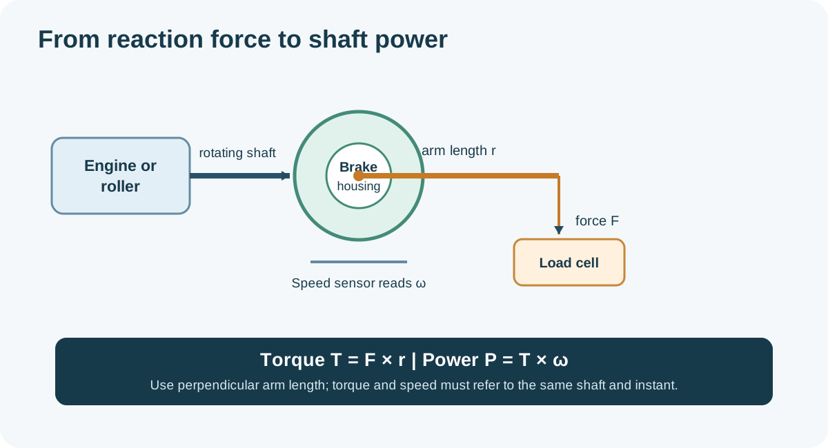
Illustrative reaction-arm measurement. A calibration load can be applied to a specified point on a suitable arm; actual construction and calibration arrangements vary. Original schematic for Tuning Wiki, CC BY 4.0.
Calibration, adjustment and verification
Calibration compares indications with reference quantity values under stated conditions, accounting for their uncertainties. The result can be a table, curve or correction. It does not automatically mean that the instrument has been adjusted.
Adjustment changes settings to bring an indication closer to the intended value. Preserve the readings before adjustment as well as after it.
Verification checks evidence against defined requirements. A decision depends on the relevant acceptance limits and, where applicable, how measurement uncertainty is treated.
The International Vocabulary of Metrology distinguishes calibration, adjustment, verification and metrological traceability. A routine zero check, a documented calibration and a full-system performance verification are related but different activities.
How a deadweight and arm create a reference torque
For a simple vertical gravitational force applied through a known perpendicular lever arm, torque T = m × g × r, with mass m in kilograms, local gravitational acceleration g in m/s² and perpendicular distance r in metres. With a nominal 20.000 kg effective load, a 0.500 m perpendicular arm and conventional standard gravity of 9.80665 m/s², the illustrative torque is 98.0665 N·m. Standard gravity in this example is a convention, not a claim that local gravity has exactly that value. For a documented measurement use the procedure's specified gravity and all relevant corrections and uncertainty.
Effective load may include a pan, hanger or arm contribution, or require a specified counterbalance. The correct lever arm is the perpendicular distance from the relevant rotational axis to the force's line of action; orientation and the exact mounting point matter. Some systems provide a calibration arm with a stamped value or a manufacturer-specific factor, so do not assume the illustrative dimensions or enter a nominal mass in a field expecting a different quantity. Dynojet's Model 224 guide describes model-specific arm placement and calibration values, while SuperFlow's Black Widow absorber manual describes a different arm and counterbalance.
Typical static checks
Dynostar A801 upgrade-kit illustration; the supplier lists a calibration weight among its contents, though packages can vary. A picture or supplied weight alone does not establish metrological traceability. Image: Dynostar, used with permission.
Prepare: identify the dyno, sensor, range, arm, loading direction and installed software. Use the manufacturer's procedure, suitable verified standards and a safe, stopped setup. Warm-up, guarding, fixtures and any disconnected components are machine-specific.
As-found zero: check the unloaded reading in the specified condition before changing settings. The system may require a tare or counterbalance; zeroing under an applied load incorrectly shifts the reference.
Apply reference points: use the prescribed arm and loads across the relevant range; record reference values and indicated values. More than one non-zero point can reveal behaviour that a single span point cannot. Repeat points and check increasing and decreasing loads when the procedure and equipment support it.
Evaluate and adjust if authorised: compare the observed values to the chosen specification. If adjustment is needed, follow the instrument maker's zero and span method and record both as-found and as-left results. Recheck the required points.
Finish and document: remove calibration apparatus and restore guards and connections under the maker's instructions. Record standards, environmental and setup conditions, direction, results, uncertainty where applicable, date and responsible person.
Do not perform these steps on a rotating assembly or improvise a procedure for suspending weights: use the supplied fixture and the machine-specific instructions. For example, the Dynojet Vector-X4000 manual describes zero and weight checks for each eddy brake, whereas other systems use different sensors and fixtures.
Linearity, hysteresis and repeatability
Linearity concerns how indication changes across the working range relative to the chosen calibration relationship. Hysteresis is a difference at the same reference load when approached from different loading directions or histories. Repeatability describes closeness under similar measurement conditions. Record the applied sequence, direction and hold time; these checks do not prove the unit's behaviour outside the tested range or under a fast transient.
A single verification load can be a useful intermediate check but cannot establish linearity over the full range. Compare with the acceptance requirements for the specific machine, procedure and test purpose; avoid applying a tolerance from another standard or instrument without checking scope. If a result is outside the chosen limits, investigate mounting, friction, sensor wiring, temperature, fixture and reference setup before changing coefficients or returning the machine to service.
Speed, environment and other channels
Speed: verify shaft or roller RPM against a suitable reference at relevant points, following the equipment maker's method. Check sensor type, tooth or pulse count, gearing, direction, signal quality and the configuration used in the calculation. A correct load-cell reading alone does not verify RPM.
Temperature, pressure and humidity: compare the channels used for correction or protection with appropriate references and document location and conditions. A weather station, intake sensor and brake-temperature sensor do not necessarily measure the same quantity. Use the correction standard and sensors applicable to the test; not every method uses every environmental input in the same way.
Other measurements: where relevant, verify pressure, lambda, thermocouple, throttle position and engine-speed channels with methods and reference equipment suited to each signal. A wideband sensor generally requires its own compatible controller, and an engine-RPM pickup is distinct from the dyno shaft-speed pickup.
Hub and multi-axle systems: identify and verify each installed speed and torque channel and its scaling. For power at multiple hubs, use each hub's torque with its corresponding speed and consistent sign at the same instant.
At any one shaft, power (kW) = torque (N·m) × speed (rpm) ÷ 9,549.3. As a separate arithmetic example, 100 N·m at 1,000 rpm is approximately 10.47 kW. A static application of 100 N·m does not itself verify dynamic power at 1,000 rpm. The US EPA engine-test work procedure describes synchronised speed and brake-torque measurement for its specific application.
Traceability and uncertainty
Metrological traceability is a property of a measurement result linked to a stated reference through a documented, unbroken chain of calibrations, with uncertainty at each step. A stamped weight, certificate or accredited laboratory name alone does not prove the traceability or fitness of the final dyno measurement: check the reference, chain, scope, uncertainties and method. The ISO guidance on calibration and laboratory competence discusses traceability, uncertainty and ISO/IEC 17025. An ISO/IEC 17025 accredited calibration, where required, should be within the provider's actual accredited scope for the quantity, range and location.
Potential contributors include calibrated mass and arm dimensions, local gravity, alignment, hanger and arm effects, sensor resolution, repeatability, loading direction, drift, temperature, electrical conditioning and speed measurement. Their effects may be correlated; assess them according to the calibration method rather than simply treating the spread of a few vehicle runs as the complete uncertainty. The JCGM Guide to the Expression of Uncertainty in Measurement discusses evaluation of uncertainty components.
What a static check cannot prove
A static arm check does not measure roller or shaft inertia, vehicle and tyre losses, dyno control response, brake cooling, timing delay between channels, atmospheric-correction implementation or the engine's true crankshaft output. During a sweep, output may be used to accelerate the rotating engine and dyno components; compensation is software- and equipment-specific. SuperFlow explains inertia determination. Coastdown checks and dynamic verification address different questions from a deadweight check; apply them only under the procedure appropriate to the machine and purpose.
A useful end-to-end check may include independently verified speed, torque and environmental channels; configuration review; specified inertia and loss checks; and repeat tests under consistent conditions. Repeatability is valuable, but repeatable readings can still share a systematic bias.
When to check and what to keep
Use the manufacturer, calibration provider, applicable test standard and facility quality system to set intervals and acceptance criteria; there is no universal interval established here. Additional checks are sensible after load-cell or sensor replacement, arm or brake work, a relocation, impact, unexpected readings, software or scaling changes, or before a critical comparison, according to the relevant procedure. If the machine fails a required check, follow the facility's process for investigation, correction and assessment of affected results.
Keep a record of the machine and channel identity, software/firmware and configuration, procedure, standard and certificate identifiers, arm and weights or other references, locations and conditions, as-found and as-left readings, corrections, uncertainty and acceptance decision, and date/person or laboratory. Retain raw and corrected test results and the applied correction method when interpreting comparisons.
Related: Measurement and interpreting results · Dynamometer control systems · Test setup and safety.
Rendered revisions
Open each version to inspect formatting, tables and photographs.
Revision 2: Dynamometer calibration and verification
Dynamometer calibration and verification establish how the measurement system responds to known references and whether it meets stated requirements. A complete result depends on more than the load cell: speed sensing, arm geometry, electronics, temperature, atmospheric measurements, data processing and the particular test procedure can all matter. An engine, roller and hub dyno may use different sensors and manufacturer procedures.
This page explains principles and planning; it is not a replacement for the exact machine's manual, an accredited procedure where required, or a competent calibration provider. Follow the manufacturer's instructions and the site's risk assessment. See measurement and interpreting results and test setup and safety.
Illustrative reaction-arm measurement. A calibration load can be applied to a specified point on a suitable arm; actual construction and calibration arrangements vary. Original schematic for Tuning Wiki, CC BY 4.0.
Calibration, adjustment and verification
Calibration compares indications with reference quantity values under stated conditions, accounting for their uncertainties. The result can be a table, curve or correction. It does not automatically mean that the instrument has been adjusted.
Adjustment changes settings to bring an indication closer to the intended value. Preserve the readings before adjustment as well as after it.
Verification checks evidence against defined requirements. A decision depends on the relevant acceptance limits and, where applicable, how measurement uncertainty is treated.
The International Vocabulary of Metrology distinguishes calibration, adjustment, verification and metrological traceability. A routine zero check, a documented calibration and a full-system performance verification are related but different activities.
How a deadweight and arm create a reference torque
For a simple vertical gravitational force applied through a known perpendicular lever arm, torque T = m × g × r, with mass m in kilograms, local gravitational acceleration g in m/s² and perpendicular distance r in metres. With a nominal 20.000 kg effective load, a 0.500 m perpendicular arm and conventional standard gravity of 9.80665 m/s², the illustrative torque is 98.0665 N·m. Standard gravity in this example is a convention, not a claim that local gravity has exactly that value. For a documented measurement use the procedure's specified gravity and all relevant corrections and uncertainty.
Effective load may include a pan, hanger or arm contribution, or require a specified counterbalance. The correct lever arm is the perpendicular distance from the relevant rotational axis to the force's line of action; orientation and the exact mounting point matter. Some systems provide a calibration arm with a stamped value or a manufacturer-specific factor, so do not assume the illustrative dimensions or enter a nominal mass in a field expecting a different quantity. Dynojet's Model 224 guide describes model-specific arm placement and calibration values, while SuperFlow's Black Widow absorber manual describes a different arm and counterbalance.
Typical static checks
Dynostar A801 upgrade-kit illustration; the supplier lists a calibration weight among its contents, though packages can vary. A picture or supplied weight alone does not establish metrological traceability. Image: Dynostar, used with permission.
Prepare: identify the dyno, sensor, range, arm, loading direction and installed software. Use the manufacturer's procedure, suitable verified standards and a safe, stopped setup. Warm-up, guarding, fixtures and any disconnected components are machine-specific.
As-found zero: check the unloaded reading in the specified condition before changing settings. The system may require a tare or counterbalance; zeroing under an applied load incorrectly shifts the reference.
Apply reference points: use the prescribed arm and loads across the relevant range; record reference values and indicated values. More than one non-zero point can reveal behaviour that a single span point cannot. Repeat points and check increasing and decreasing loads when the procedure and equipment support it.
Evaluate and adjust if authorised: compare the observed values to the chosen specification. If adjustment is needed, follow the instrument maker's zero and span method and record both as-found and as-left results. Recheck the required points.
Finish and document: remove calibration apparatus and restore guards and connections under the maker's instructions. Record standards, environmental and setup conditions, direction, results, uncertainty where applicable, date and responsible person.
Do not perform these steps on a rotating assembly or improvise a procedure for suspending weights: use the supplied fixture and the machine-specific instructions. For example, the Dynojet Vector-X4000 manual describes zero and weight checks for each eddy brake, whereas other systems use different sensors and fixtures.
Linearity, hysteresis and repeatability
Linearity concerns how indication changes across the working range relative to the chosen calibration relationship. Hysteresis is a difference at the same reference load when approached from different loading directions or histories. Repeatability describes closeness under similar measurement conditions. Record the applied sequence, direction and hold time; these checks do not prove the unit's behaviour outside the tested range or under a fast transient.
A single verification load can be a useful intermediate check but cannot establish linearity over the full range. Compare with the acceptance requirements for the specific machine, procedure and test purpose; avoid applying a tolerance from another standard or instrument without checking scope. If a result is outside the chosen limits, investigate mounting, friction, sensor wiring, temperature, fixture and reference setup before changing coefficients or returning the machine to service.
Speed, environment and other channels
Speed: verify shaft or roller RPM against a suitable reference at relevant points, following the equipment maker's method. Check sensor type, tooth or pulse count, gearing, direction, signal quality and the configuration used in the calculation. A correct load-cell reading alone does not verify RPM.
Temperature, pressure and humidity: compare the channels used for correction or protection with appropriate references and document location and conditions. A weather station, intake sensor and brake-temperature sensor do not necessarily measure the same quantity. Use the correction standard and sensors applicable to the test; not every method uses every environmental input in the same way.
Other measurements: where relevant, verify pressure, lambda, thermocouple, throttle position and engine-speed channels with methods and reference equipment suited to each signal. A wideband sensor generally requires its own compatible controller, and an engine-RPM pickup is distinct from the dyno shaft-speed pickup.
Hub and multi-axle systems: identify and verify each installed speed and torque channel and its scaling. For power at multiple hubs, use each hub's torque with its corresponding speed and consistent sign at the same instant.
At any one shaft, power (kW) = torque (N·m) × speed (rpm) ÷ 9,549.3. As a separate arithmetic example, 100 N·m at 1,000 rpm is approximately 10.47 kW. A static application of 100 N·m does not itself verify dynamic power at 1,000 rpm. The US EPA engine-test work procedure describes synchronised speed and brake-torque measurement for its specific application.
Traceability and uncertainty
Metrological traceability is a property of a measurement result linked to a stated reference through a documented, unbroken chain of calibrations, with uncertainty at each step. A stamped weight, certificate or accredited laboratory name alone does not prove the traceability or fitness of the final dyno measurement: check the reference, chain, scope, uncertainties and method. The ISO guidance on calibration and laboratory competence discusses traceability, uncertainty and ISO/IEC 17025. An ISO/IEC 17025 accredited calibration, where required, should be within the provider's actual accredited scope for the quantity, range and location.
Potential contributors include calibrated mass and arm dimensions, local gravity, alignment, hanger and arm effects, sensor resolution, repeatability, loading direction, drift, temperature, electrical conditioning and speed measurement. Their effects may be correlated; assess them according to the calibration method rather than simply treating the spread of a few vehicle runs as the complete uncertainty. The JCGM Guide to the Expression of Uncertainty in Measurement discusses evaluation of uncertainty components.
What a static check cannot prove
A static arm check does not measure roller or shaft inertia, vehicle and tyre losses, dyno control response, brake cooling, timing delay between channels, atmospheric-correction implementation or the engine's true crankshaft output. During a sweep, output may be used to accelerate the rotating engine and dyno components; compensation is software- and equipment-specific. SuperFlow explains inertia determination. Coastdown checks and dynamic verification address different questions from a deadweight check; apply them only under the procedure appropriate to the machine and purpose.
A useful end-to-end check may include independently verified speed, torque and environmental channels; configuration review; specified inertia and loss checks; and repeat tests under consistent conditions. Repeatability is valuable, but repeatable readings can still share a systematic bias.
When to check and what to keep
Use the manufacturer, calibration provider, applicable test standard and facility quality system to set intervals and acceptance criteria; there is no universal interval established here. Additional checks are sensible after load-cell or sensor replacement, arm or brake work, a relocation, impact, unexpected readings, software or scaling changes, or before a critical comparison, according to the relevant procedure. If the machine fails a required check, follow the facility's process for investigation, correction and assessment of affected results.
Keep a record of the machine and channel identity, software/firmware and configuration, procedure, standard and certificate identifiers, arm and weights or other references, locations and conditions, as-found and as-left readings, corrections, uncertainty and acceptance decision, and date/person or laboratory. Retain raw and corrected test results and the applied correction method when interpreting comparisons.
Revision 2: Dynamometer calibration and verification
Dynamometer calibration and verification establish how the measurement system responds to known references and whether it meets stated requirements. A complete result depends on more than the load cell: speed sensing, arm geometry, electronics, temperature, atmospheric measurements, data processing and the particular test procedure can all matter. An engine, roller and hub dyno may use different sensors and manufacturer procedures.
This page explains principles and planning; it is not a replacement for the exact machine's manual, an accredited procedure where required, or a competent calibration provider. Follow the manufacturer's instructions and the site's risk assessment. See measurement and interpreting results and test setup and safety.
Illustrative reaction-arm measurement. A calibration load can be applied to a specified point on a suitable arm; actual construction and calibration arrangements vary. Original schematic for Tuning Wiki, CC BY 4.0.
Calibration, adjustment and verification
Calibration compares indications with reference quantity values under stated conditions, accounting for their uncertainties. The result can be a table, curve or correction. It does not automatically mean that the instrument has been adjusted.
Adjustment changes settings to bring an indication closer to the intended value. Preserve the readings before adjustment as well as after it.
Verification checks evidence against defined requirements. A decision depends on the relevant acceptance limits and, where applicable, how measurement uncertainty is treated.
The International Vocabulary of Metrology distinguishes calibration, adjustment, verification and metrological traceability. A routine zero check, a documented calibration and a full-system performance verification are related but different activities.
How a deadweight and arm create a reference torque
For a simple vertical gravitational force applied through a known perpendicular lever arm, torque T = m × g × r, with mass m in kilograms, local gravitational acceleration g in m/s² and perpendicular distance r in metres. With a nominal 20.000 kg effective load, a 0.500 m perpendicular arm and conventional standard gravity of 9.80665 m/s², the illustrative torque is 98.0665 N·m. Standard gravity in this example is a convention, not a claim that local gravity has exactly that value. For a documented measurement use the procedure's specified gravity and all relevant corrections and uncertainty.
Effective load may include a pan, hanger or arm contribution, or require a specified counterbalance. The correct lever arm is the perpendicular distance from the relevant rotational axis to the force's line of action; orientation and the exact mounting point matter. Some systems provide a calibration arm with a stamped value or a manufacturer-specific factor, so do not assume the illustrative dimensions or enter a nominal mass in a field expecting a different quantity. Dynojet's Model 224 guide describes model-specific arm placement and calibration values, while SuperFlow's Black Widow absorber manual describes a different arm and counterbalance.
Typical static checks
Dynostar A801 upgrade-kit illustration; the supplier lists a calibration weight among its contents, though packages can vary. A picture or supplied weight alone does not establish metrological traceability. Image: Dynostar, used with permission.
Prepare: identify the dyno, sensor, range, arm, loading direction and installed software. Use the manufacturer's procedure, suitable verified standards and a safe, stopped setup. Warm-up, guarding, fixtures and any disconnected components are machine-specific.
As-found zero: check the unloaded reading in the specified condition before changing settings. The system may require a tare or counterbalance; zeroing under an applied load incorrectly shifts the reference.
Apply reference points: use the prescribed arm and loads across the relevant range; record reference values and indicated values. More than one non-zero point can reveal behaviour that a single span point cannot. Repeat points and check increasing and decreasing loads when the procedure and equipment support it.
Evaluate and adjust if authorised: compare the observed values to the chosen specification. If adjustment is needed, follow the instrument maker's zero and span method and record both as-found and as-left results. Recheck the required points.
Finish and document: remove calibration apparatus and restore guards and connections under the maker's instructions. Record standards, environmental and setup conditions, direction, results, uncertainty where applicable, date and responsible person.
Do not perform these steps on a rotating assembly or improvise a procedure for suspending weights: use the supplied fixture and the machine-specific instructions. For example, the Dynojet Vector-X4000 manual describes zero and weight checks for each eddy brake, whereas other systems use different sensors and fixtures.
Linearity, hysteresis and repeatability
Linearity concerns how indication changes across the working range relative to the chosen calibration relationship. Hysteresis is a difference at the same reference load when approached from different loading directions or histories. Repeatability describes closeness under similar measurement conditions. Record the applied sequence, direction and hold time; these checks do not prove the unit's behaviour outside the tested range or under a fast transient.
A single verification load can be a useful intermediate check but cannot establish linearity over the full range. Compare with the acceptance requirements for the specific machine, procedure and test purpose; avoid applying a tolerance from another standard or instrument without checking scope. If a result is outside the chosen limits, investigate mounting, friction, sensor wiring, temperature, fixture and reference setup before changing coefficients or returning the machine to service.
Speed, environment and other channels
Speed: verify shaft or roller RPM against a suitable reference at relevant points, following the equipment maker's method. Check sensor type, tooth or pulse count, gearing, direction, signal quality and the configuration used in the calculation. A correct load-cell reading alone does not verify RPM.
Temperature, pressure and humidity: compare the channels used for correction or protection with appropriate references and document location and conditions. A weather station, intake sensor and brake-temperature sensor do not necessarily measure the same quantity. Use the correction standard and sensors applicable to the test; not every method uses every environmental input in the same way.
Other measurements: where relevant, verify pressure, lambda, thermocouple, throttle position and engine-speed channels with methods and reference equipment suited to each signal. A wideband sensor generally requires its own compatible controller, and an engine-RPM pickup is distinct from the dyno shaft-speed pickup.
Hub and multi-axle systems: identify and verify each installed speed and torque channel and its scaling. For power at multiple hubs, use each hub's torque with its corresponding speed and consistent sign at the same instant.
At any one shaft, power (kW) = torque (N·m) × speed (rpm) ÷ 9,549.3. As a separate arithmetic example, 100 N·m at 1,000 rpm is approximately 10.47 kW. A static application of 100 N·m does not itself verify dynamic power at 1,000 rpm. The US EPA engine-test work procedure describes synchronised speed and brake-torque measurement for its specific application.
Traceability and uncertainty
Metrological traceability is a property of a measurement result linked to a stated reference through a documented, unbroken chain of calibrations, with uncertainty at each step. A stamped weight, certificate or accredited laboratory name alone does not prove the traceability or fitness of the final dyno measurement: check the reference, chain, scope, uncertainties and method. The ISO guidance on calibration and laboratory competence discusses traceability, uncertainty and ISO/IEC 17025. An ISO/IEC 17025 accredited calibration, where required, should be within the provider's actual accredited scope for the quantity, range and location.
Potential contributors include calibrated mass and arm dimensions, local gravity, alignment, hanger and arm effects, sensor resolution, repeatability, loading direction, drift, temperature, electrical conditioning and speed measurement. Their effects may be correlated; assess them according to the calibration method rather than simply treating the spread of a few vehicle runs as the complete uncertainty. The JCGM Guide to the Expression of Uncertainty in Measurement discusses evaluation of uncertainty components.
What a static check cannot prove
A static arm check does not measure roller or shaft inertia, vehicle and tyre losses, dyno control response, brake cooling, timing delay between channels, atmospheric-correction implementation or the engine's true crankshaft output. During a sweep, output may be used to accelerate the rotating engine and dyno components; compensation is software- and equipment-specific. SuperFlow explains inertia determination. Coastdown checks and dynamic verification address different questions from a deadweight check; apply them only under the procedure appropriate to the machine and purpose.
A useful end-to-end check may include independently verified speed, torque and environmental channels; configuration review; specified inertia and loss checks; and repeat tests under consistent conditions. Repeatability is valuable, but repeatable readings can still share a systematic bias.
When to check and what to keep
Use the manufacturer, calibration provider, applicable test standard and facility quality system to set intervals and acceptance criteria; there is no universal interval established here. Additional checks are sensible after load-cell or sensor replacement, arm or brake work, a relocation, impact, unexpected readings, software or scaling changes, or before a critical comparison, according to the relevant procedure. If the machine fails a required check, follow the facility's process for investigation, correction and assessment of affected results.
Keep a record of the machine and channel identity, software/firmware and configuration, procedure, standard and certificate identifiers, arm and weights or other references, locations and conditions, as-found and as-left readings, corrections, uncertainty and acceptance decision, and date/person or laboratory. Retain raw and corrected test results and the applied correction method when interpreting comparisons.