Removed text is struck through; added text is highlighted.
Pentar Kloft Retarder makes electromagnetic retarders, including a high-speed range and custom long shafts for dynamometer applications. These are absorber components; a complete dynamometer additionally needs a suitable frame, coupling, measurement, controls and cooling provision. The name on the brake does not by itself identify the complete dyno manufacturer.
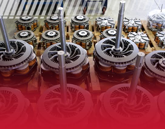
Retarder assemblies shown in Pentar Kloft's dynamometer-page gallery; individual model and ratings are not identified in the image. Image: Pentar Kloft Retarder, used with permission.
Company and history
Pentar Kloft says its retarder business began in Germany and describes engineering and assembly in Frankfurt and production in Navarra, Spain. It describes over 30 years of sector experience; that claim refers to the business history and does not establish the incorporation date of every legal entity. Pentar company information. Spain's official commercial register records the incorporation of Pentar Kloft Retarder S.L. with operations commencing on 27 November 2015. BORME, 18 December 2015.
How the absorber works
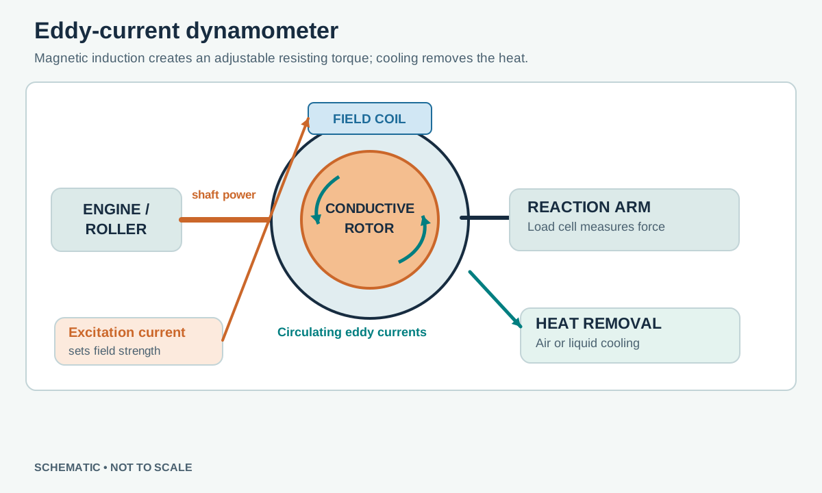
Illustrative eddy-current dynamometer, not a model-specific cutaway. Induced-current paths and torque-sensor placement depend on the design. Original schematic for Tuning Wiki, CC BY 4.0.
As the driven shaft turns, relative movement through an excited magnetic field causes circulating currents in conductive material. The resulting magnetic reaction opposes rotation and dissipates absorbed shaft power as heat. The excitation current controls the field and therefore influences brake torque within the actual speed and temperature envelope. This schematic is a general principle; the exact arrangement differs among designs.
At zero speed a passive eddy-current retarder cannot provide eddy-current holding torque. It cannot drive the test piece or return absorbed shaft power to the grid. A dyno can measure brake reaction with a suitable load cell and calculate power using matching shaft speed; sensors and controller are part of the complete installation, not automatically included with a retarder. Acceleration tests require the effect of rotating inertia and losses to be considered. See eddy-current dynamometers.
Range and options
The manufacturer's dynamometer page describes custom long shafts, high-speed bearings, special rotor alloys and aluminium or copper excitation coils. It lists 12, 24, 96 and 192 V versions; select the exact winding and driver together, not by voltage alone. The supplier's axial retarder page also describes use in vehicles and dynamometers and shows products labelled PK1, P5, P7, P10 and P11. Those names appear on product images; the source does not establish that every listed item is a high-speed dyno-rated variant, nor give a dyno rating for each. Confirm the particular design and specification with the manufacturer.
Integrating and controlling one
Mechanical fit: confirm shaft ends, maximum speed, bearings, balance, couplings and mounting for the specified brake and duty.Excitation: identify winding voltage and current, and select a power stage with suitable current control and inductive-load protection. A low-power controller output may need an appropriate external driver.Heat: ensure adequate cooling and monitoring for the manufacturer's continuous and short-duration ratings. Power capacity depends on speed, duration and cooling, rather than one universal number.Control and torque: a dyno integrator selects speed sensing, torque measurement and calibration, feedback, interlocks and software. The cited supplier pages do not identify a particular factory dyno controller, so compatibility with a controller must be established for the specific winding and installation.
See dynamometer control systems, eddy-current hub dynamometers and Frenelsa dynamometer brakes.
Open each version to inspect formatting, tables and photographs.
Revision 1: Pentar Kloft Dynamometer Brakes
Pentar Kloft Retarder makes electromagnetic retarders, including a high-speed range and custom long shafts for dynamometer applications. These are absorber components; a complete dynamometer additionally needs a suitable frame, coupling, measurement, controls and cooling provision. The name on the brake does not by itself identify the complete dyno manufacturer.
Retarder assemblies shown in Pentar Kloft's dynamometer-page gallery; individual model and ratings are not identified in the image. Image: Pentar Kloft Retarder, used with permission.
Company and history
Pentar Kloft says its retarder business began in Germany and describes engineering and assembly in Frankfurt and production in Navarra, Spain. It describes over 30 years of sector experience; that claim refers to the business history and does not establish the incorporation date of every legal entity. Pentar company information. Spain's official commercial register records the incorporation of Pentar Kloft Retarder S.L. with operations commencing on 27 November 2015. BORME, 18 December 2015.
How the absorber works
Illustrative eddy-current dynamometer, not a model-specific cutaway. Induced-current paths and torque-sensor placement depend on the design. Original schematic for Tuning Wiki, CC BY 4.0.
As the driven shaft turns, relative movement through an excited magnetic field causes circulating currents in conductive material. The resulting magnetic reaction opposes rotation and dissipates absorbed shaft power as heat. The excitation current controls the field and therefore influences brake torque within the actual speed and temperature envelope. This schematic is a general principle; the exact arrangement differs among designs.
At zero speed a passive eddy-current retarder cannot provide eddy-current holding torque. It cannot drive the test piece or return absorbed shaft power to the grid. A dyno can measure brake reaction with a suitable load cell and calculate power using matching shaft speed; sensors and controller are part of the complete installation, not automatically included with a retarder. Acceleration tests require the effect of rotating inertia and losses to be considered. See eddy-current dynamometers.
Range and options
The manufacturer's dynamometer page describes custom long shafts, high-speed bearings, special rotor alloys and aluminium or copper excitation coils. It lists 12, 24, 96 and 192 V versions; select the exact winding and driver together, not by voltage alone. The supplier's axial retarder page also describes use in vehicles and dynamometers and shows products labelled PK1, P5, P7, P10 and P11. Those names appear on product images; the source does not establish that every listed item is a high-speed dyno-rated variant, nor give a dyno rating for each. Confirm the particular design and specification with the manufacturer.
Integrating and controlling one
Mechanical fit: confirm shaft ends, maximum speed, bearings, balance, couplings and mounting for the specified brake and duty.
Excitation: identify winding voltage and current, and select a power stage with suitable current control and inductive-load protection. A low-power controller output may need an appropriate external driver.
Heat: ensure adequate cooling and monitoring for the manufacturer's continuous and short-duration ratings. Power capacity depends on speed, duration and cooling, rather than one universal number.
Control and torque: a dyno integrator selects speed sensing, torque measurement and calibration, feedback, interlocks and software. The cited supplier pages do not identify a particular factory dyno controller, so compatibility with a controller must be established for the specific winding and installation.
Pentar Kloft Retarder makes electromagnetic retarders, including a high-speed range and custom long shafts for dynamometer applications. These are absorber components; a complete dynamometer additionally needs a suitable frame, coupling, measurement, controls and cooling provision. The name on the brake does not by itself identify the complete dyno manufacturer.
Retarder assemblies shown in Pentar Kloft's dynamometer-page gallery; individual model and ratings are not identified in the image. Image: Pentar Kloft Retarder, used with permission.
Company and history
Pentar Kloft says its retarder business began in Germany and describes engineering and assembly in Frankfurt and production in Navarra, Spain. It describes over 30 years of sector experience; that claim refers to the business history and does not establish the incorporation date of every legal entity. Pentar company information. Spain's official commercial register records the incorporation of Pentar Kloft Retarder S.L. with operations commencing on 27 November 2015. BORME, 18 December 2015.
How the absorber works
Illustrative eddy-current dynamometer, not a model-specific cutaway. Induced-current paths and torque-sensor placement depend on the design. Original schematic for Tuning Wiki, CC BY 4.0.
As the driven shaft turns, relative movement through an excited magnetic field causes circulating currents in conductive material. The resulting magnetic reaction opposes rotation and dissipates absorbed shaft power as heat. The excitation current controls the field and therefore influences brake torque within the actual speed and temperature envelope. This schematic is a general principle; the exact arrangement differs among designs.
At zero speed a passive eddy-current retarder cannot provide eddy-current holding torque. It cannot drive the test piece or return absorbed shaft power to the grid. A dyno can measure brake reaction with a suitable load cell and calculate power using matching shaft speed; sensors and controller are part of the complete installation, not automatically included with a retarder. Acceleration tests require the effect of rotating inertia and losses to be considered. See eddy-current dynamometers.
Range and options
The manufacturer's dynamometer page describes custom long shafts, high-speed bearings, special rotor alloys and aluminium or copper excitation coils. It lists 12, 24, 96 and 192 V versions; select the exact winding and driver together, not by voltage alone. The supplier's axial retarder page also describes use in vehicles and dynamometers and shows products labelled PK1, P5, P7, P10 and P11. Those names appear on product images; the source does not establish that every listed item is a high-speed dyno-rated variant, nor give a dyno rating for each. Confirm the particular design and specification with the manufacturer.
Integrating and controlling one
Mechanical fit: confirm shaft ends, maximum speed, bearings, balance, couplings and mounting for the specified brake and duty.
Excitation: identify winding voltage and current, and select a power stage with suitable current control and inductive-load protection. A low-power controller output may need an appropriate external driver.
Heat: ensure adequate cooling and monitoring for the manufacturer's continuous and short-duration ratings. Power capacity depends on speed, duration and cooling, rather than one universal number.
Control and torque: a dyno integrator selects speed sensing, torque measurement and calibration, feedback, interlocks and software. The cited supplier pages do not identify a particular factory dyno controller, so compatibility with a controller must be established for the specific winding and installation.