Removed text is struck through; added text is highlighted.
Holley Sniper EFI Quadrajet is a carburettor-replacement throttle-body fuel-injection system with integrated electronic control. The handheld is a setup/display device, and the system also requires appropriate fuel delivery, wiring and sensors.
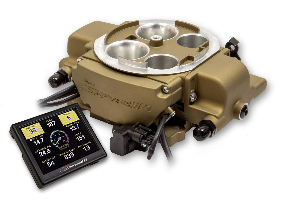
Holley Holley Sniper EFI Quadrajet family illustration from its installation manual, cover; finish and injector count vary with part number. Manufacturer photograph reproduced with permission.
Applications and versions
Holley’s Quadrajet system is intended to replace a Rochester Quadrajet-pattern four-barrel carburettor. Verify manifold, throttle linkage, fuel supply and air cleaner against the vehicle and the instructions.
Four-injector throttle-body EFI with integrated ECU. Holley's comparison lists up to 500 hp naturally aspirated; 550-867, 550-868 and 550-869 are finish variants. Model numbers: 550-867 / 550-868 / 550-869. See Holley’s Sniper model comparison.
Manufacturer harness connections
The model-specific Holley installation manual, PDF page 9, identifies the seven-way 558-490 main harness and ten-way 558-491 I/O harness below. The ten-way table has eight populated wires; the source does not assign the remaining two cavities. Outputs are relay-control signals: use the source for ratings, ignition configuration and the connector view. The throttle body, 4-pin CAN handheld connection, coolant sensor and oxygen sensor are separate connections.
Seven-way main harness, 558-490
PinWire colourManufacturer functionAVioletCrank signal positiveBDark greenCrank signal negativeCBlueFuel-pump supply from relayDYellowCoil-negative engine-speed inputERedBattery positiveFPinkSwitched ignition +12 VGBlackBattery negative
The correct fuel pump, filters, sensor placement and ignition setup depend on the kit and vehicle. An RPM input alone does not establish ECU timing control; consult the manual and identify the ignition hardware before wiring.
Rendered revisions
Open each version to inspect formatting, tables and photographs.
Revision 1: Holley Sniper EFI Quadrajet
Holley Sniper EFI Quadrajet is a carburettor-replacement throttle-body fuel-injection system with integrated electronic control. The handheld is a setup/display device, and the system also requires appropriate fuel delivery, wiring and sensors.
Holley Holley Sniper EFI Quadrajet family illustration from its installation manual, cover; finish and injector count vary with part number. Manufacturer photograph reproduced with permission.
Applications and versions
Holley’s Quadrajet system is intended to replace a Rochester Quadrajet-pattern four-barrel carburettor. Verify manifold, throttle linkage, fuel supply and air cleaner against the vehicle and the instructions.
Four-injector throttle-body EFI with integrated ECU. Holley's comparison lists up to 500 hp naturally aspirated; 550-867, 550-868 and 550-869 are finish variants. Model numbers: 550-867 / 550-868 / 550-869. See Holley’s Sniper model comparison.
Manufacturer harness connections
The model-specific Holley installation manual, PDF page 9, identifies the seven-way 558-490 main harness and ten-way 558-491 I/O harness below. The ten-way table has eight populated wires; the source does not assign the remaining two cavities. Outputs are relay-control signals: use the source for ratings, ignition configuration and the connector view. The throttle body, 4-pin CAN handheld connection, coolant sensor and oxygen sensor are separate connections.
Seven-way main harness, 558-490
Pin
Wire colour
Manufacturer function
A
Violet
Crank signal positive
B
Dark green
Crank signal negative
C
Blue
Fuel-pump supply from relay
D
Yellow
Coil-negative engine-speed input
E
Red
Battery positive
F
Pink
Switched ignition +12 V
G
Black
Battery negative
Ten-way I/O harness, 558-491
Pin
Wire colour
Manufacturer function
A
Orange
Input 1, ground-triggered A/C
B
Yellow
Input 2, programmable ground input
C
Light blue
Output 1, fan 1 relay trigger
D
Light green
Output 2, fan 2 relay trigger
E
Grey
Output 6, A/C shutdown relay trigger
F
White
Points output for compatible ignition
G
Dark brown
Tachometer output
H
Tan
Digital gauge output
Installation and ignition
The correct fuel pump, filters, sensor placement and ignition setup depend on the kit and vehicle. An RPM input alone does not establish ECU timing control; consult the manual and identify the ignition hardware before wiring.
Revision 1: Holley Sniper EFI Quadrajet
Holley Sniper EFI Quadrajet is a carburettor-replacement throttle-body fuel-injection system with integrated electronic control. The handheld is a setup/display device, and the system also requires appropriate fuel delivery, wiring and sensors.
Holley Holley Sniper EFI Quadrajet family illustration from its installation manual, cover; finish and injector count vary with part number. Manufacturer photograph reproduced with permission.
Applications and versions
Holley’s Quadrajet system is intended to replace a Rochester Quadrajet-pattern four-barrel carburettor. Verify manifold, throttle linkage, fuel supply and air cleaner against the vehicle and the instructions.
Four-injector throttle-body EFI with integrated ECU. Holley's comparison lists up to 500 hp naturally aspirated; 550-867, 550-868 and 550-869 are finish variants. Model numbers: 550-867 / 550-868 / 550-869. See Holley’s Sniper model comparison.
Manufacturer harness connections
The model-specific Holley installation manual, PDF page 9, identifies the seven-way 558-490 main harness and ten-way 558-491 I/O harness below. The ten-way table has eight populated wires; the source does not assign the remaining two cavities. Outputs are relay-control signals: use the source for ratings, ignition configuration and the connector view. The throttle body, 4-pin CAN handheld connection, coolant sensor and oxygen sensor are separate connections.
Seven-way main harness, 558-490
Pin
Wire colour
Manufacturer function
A
Violet
Crank signal positive
B
Dark green
Crank signal negative
C
Blue
Fuel-pump supply from relay
D
Yellow
Coil-negative engine-speed input
E
Red
Battery positive
F
Pink
Switched ignition +12 V
G
Black
Battery negative
Ten-way I/O harness, 558-491
Pin
Wire colour
Manufacturer function
A
Orange
Input 1, ground-triggered A/C
B
Yellow
Input 2, programmable ground input
C
Light blue
Output 1, fan 1 relay trigger
D
Light green
Output 2, fan 2 relay trigger
E
Grey
Output 6, A/C shutdown relay trigger
F
White
Points output for compatible ignition
G
Dark brown
Tachometer output
H
Tan
Digital gauge output
Installation and ignition
The correct fuel pump, filters, sensor placement and ignition setup depend on the kit and vehicle. An RPM input alone does not establish ECU timing control; consult the manual and identify the ignition hardware before wiring.