Removed text is struck through; added text is highlighted.
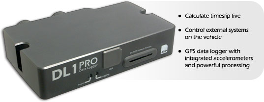
A standalone professional GPS data logger with an aluminium enclosure, sensor inputs and computer download interfaces.
Image: Race Technology, reproduced with permission; manufacturer source.
Specifications and capabilities
The PRO uses a removable SD card and front USB connection. It shares logging functions with the sealed WP, but their enclosures, storage and physical USB access differ. Manufacturer specifications and documentation.
Data analysis software
Stop logging and load the .RUN file from the removable SD card into Race Technology Analysis for track, graph and lap comparison. Manufacturer documentation.
Race Technology Analysis example; the available channels and video depend on the recording and enabled options. Image: Race Technology, reproduced with permission; manufacturer source.
Download Race Technology software for Windows. Check the current version and any licence or hardware requirements; some advanced functions require a unit-linked licence. See the Race Technology software overview for features and licensing.
Pinouts and cabling
Selected 19-way connector positions as labelled by the manufacturer (letter and pin number):
Selected 24-way positions: 14 CAN 1 low, 20 CAN 1 high, 19 CAN 2 low and 22 CAN 2 high. See the source for all remaining positions and connector orientation. On PRO, the listed connector USB positions are not connected; use its front USB port.
Manufacturer connection reference.
Check the connector number, version and options on the actual unit against the manufacturer's documentation before wiring. Disconnect power before changing connections.
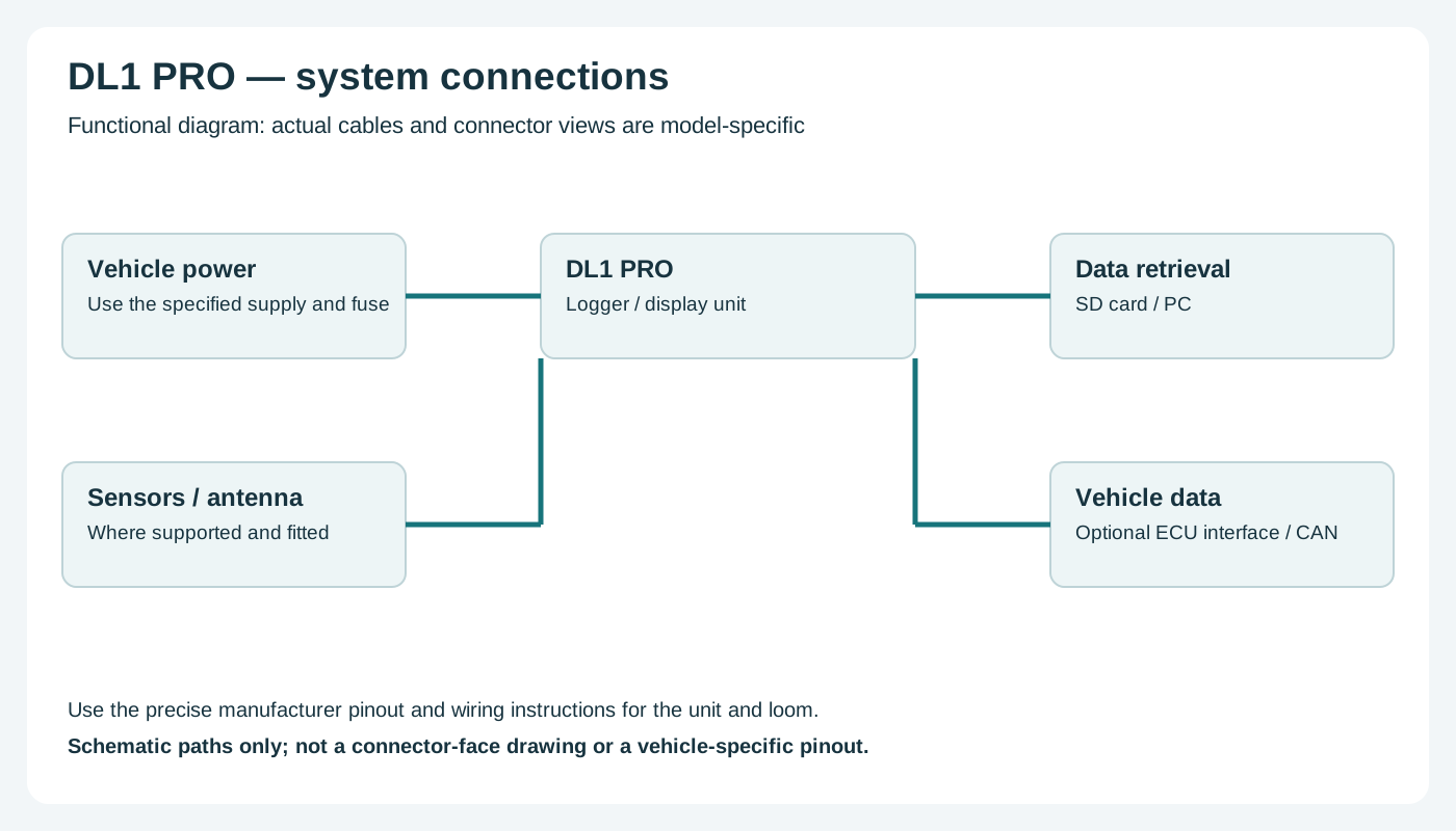
Wiring overview
Functional wiring overview; not a connector-face diagram. Confirm actual connections with the manufacturer.
Return to the Race Technology manufacturer page.
Rendered revisions
Open each version to inspect formatting, tables and photographs.
Revision 2: Race Technology DL1 PRO
A standalone professional GPS data logger with an aluminium enclosure, sensor inputs and computer download interfaces.
The PRO uses a removable SD card and front USB connection. It shares logging functions with the sealed WP, but their enclosures, storage and physical USB access differ. Manufacturer specifications and documentation.
Data analysis software
Stop logging and load the .RUN file from the removable SD card into Race Technology Analysis for track, graph and lap comparison. Manufacturer documentation.
Race Technology Analysis example; the available channels and video depend on the recording and enabled options. Image: Race Technology, reproduced with permission; manufacturer source.
Selected 19-way connector positions as labelled by the manufacturer (letter and pin number):
Pin / terminal
Function
A / 1
Analogue 1
B / 2
Analogue 2
C / 3
Sensor ground
D / 4
9–24 V power
E / 5
Ground
F / 6
High-level RPM
G / 7
RPM ground
I / 9
+5 V reference
P / 15
Low-level RPM
T / 18
Frequency 1
U / 19
Frequency 2
Selected 24-way positions: 14 CAN 1 low, 20 CAN 1 high, 19 CAN 2 low and 22 CAN 2 high. See the source for all remaining positions and connector orientation. On PRO, the listed connector USB positions are not connected; use its front USB port.
Check the connector number, version and options on the actual unit against the manufacturer's documentation before wiring. Disconnect power before changing connections.
Wiring overview
Functional wiring overview; not a connector-face diagram. Confirm actual connections with the manufacturer.
The PRO uses a removable SD card and front USB connection. It shares logging functions with the sealed WP, but their enclosures, storage and physical USB access differ. Manufacturer specifications and documentation.
Data analysis software
Stop logging and load the .RUN file from the removable SD card into Race Technology Analysis for track, graph and lap comparison. Manufacturer documentation.
Race Technology Analysis example; the available channels and video depend on the recording and enabled options. Image: Race Technology, reproduced with permission; manufacturer source.
Selected 19-way connector positions as labelled by the manufacturer (letter and pin number):
Pin / terminal
Function
A / 1
Analogue 1
B / 2
Analogue 2
C / 3
Sensor ground
D / 4
9–24 V power
E / 5
Ground
F / 6
High-level RPM
G / 7
RPM ground
I / 9
+5 V reference
P / 15
Low-level RPM
T / 18
Frequency 1
U / 19
Frequency 2
Selected 24-way positions: 14 CAN 1 low, 20 CAN 1 high, 19 CAN 2 low and 22 CAN 2 high. See the source for all remaining positions and connector orientation. On PRO, the listed connector USB positions are not connected; use its front USB port.
Check the connector number, version and options on the actual unit against the manufacturer's documentation before wiring. Disconnect power before changing connections.
Wiring overview
Functional wiring overview; not a connector-face diagram. Confirm actual connections with the manufacturer.