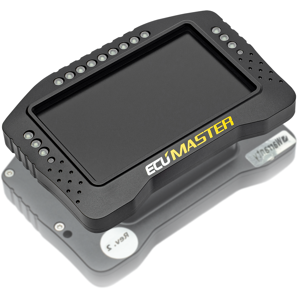
The ADU5 is ECUMASTER's five-inch standard-connector dash and USB data logger. The manufacturer lists brightness of 600 cd/m² and weight 408 g; enclosure protection depends on revision, with Rev.2 listed IP65. ECUMASTER ADU specification.
Data analysis software
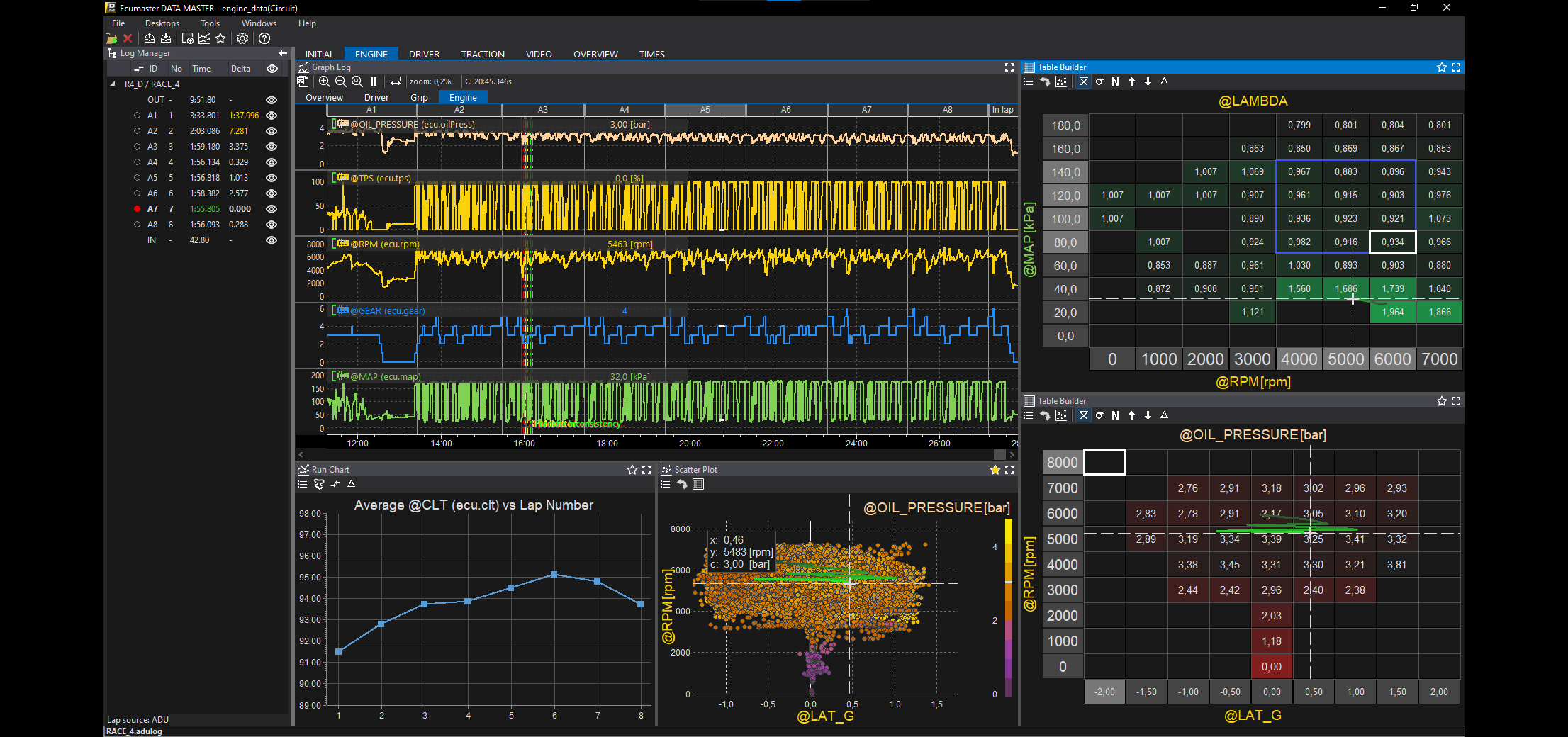
Record the configured channels to the ADU's USB drive, then open the file in ECUMASTER Data Master to compare laps, graph channels and analyse logged data. Video synchronisation requires a suitable recording. Download Data Master and the manual; ADU USB logging instructions. Configure the ADU using its separate ADU software package. Available channels depend on the configured logger, sensors and ECU data.
See the ECUMASTER analysis software overview.
Specifications and logging
The ADU combines a configurable TFT dashboard, alarms and 15 RGB LEDs with acquisition of vehicle and sensor data. Its inputs include eight 0–5 V analogue channels, eight digital/frequency channels, two low-side outputs, a 0–5 V analogue output, CAN 2.0 A/B and RS232. GPS lap timing requires a suitable external GPS source. The manufacturer’s specification gives an operating range of 6–22 V and 3-axis accelerometer and gyroscope.
Channels can be logged to an external USB flash drive at up to 500 Hz, subject to channel and source rates. Configure channels, trigger and storage using the USB logging guide. Data Master analyses compatible recordings. An ECU's CAN message list and rate are separate limitations: confirm protocol, baud rate and channel availability.
Documentation discrepancy: ECUMASTER's product page states 800 × 480 pixels; its catalogue states 800 × 600. Verify the resolution for the exact product and revision with ECUMASTER.
Connector and pinout
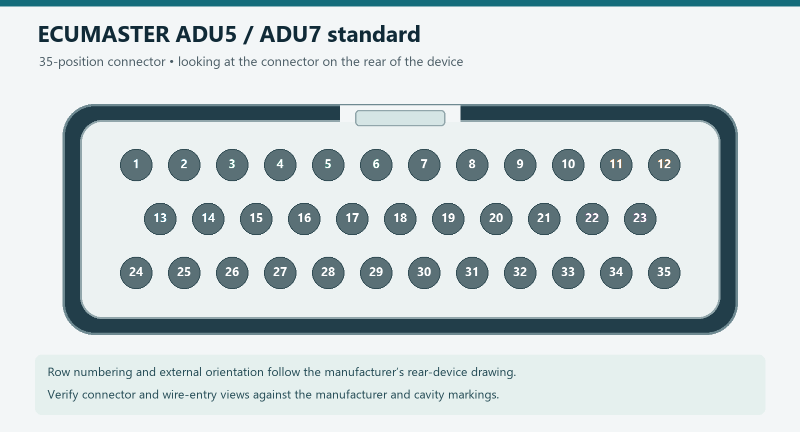
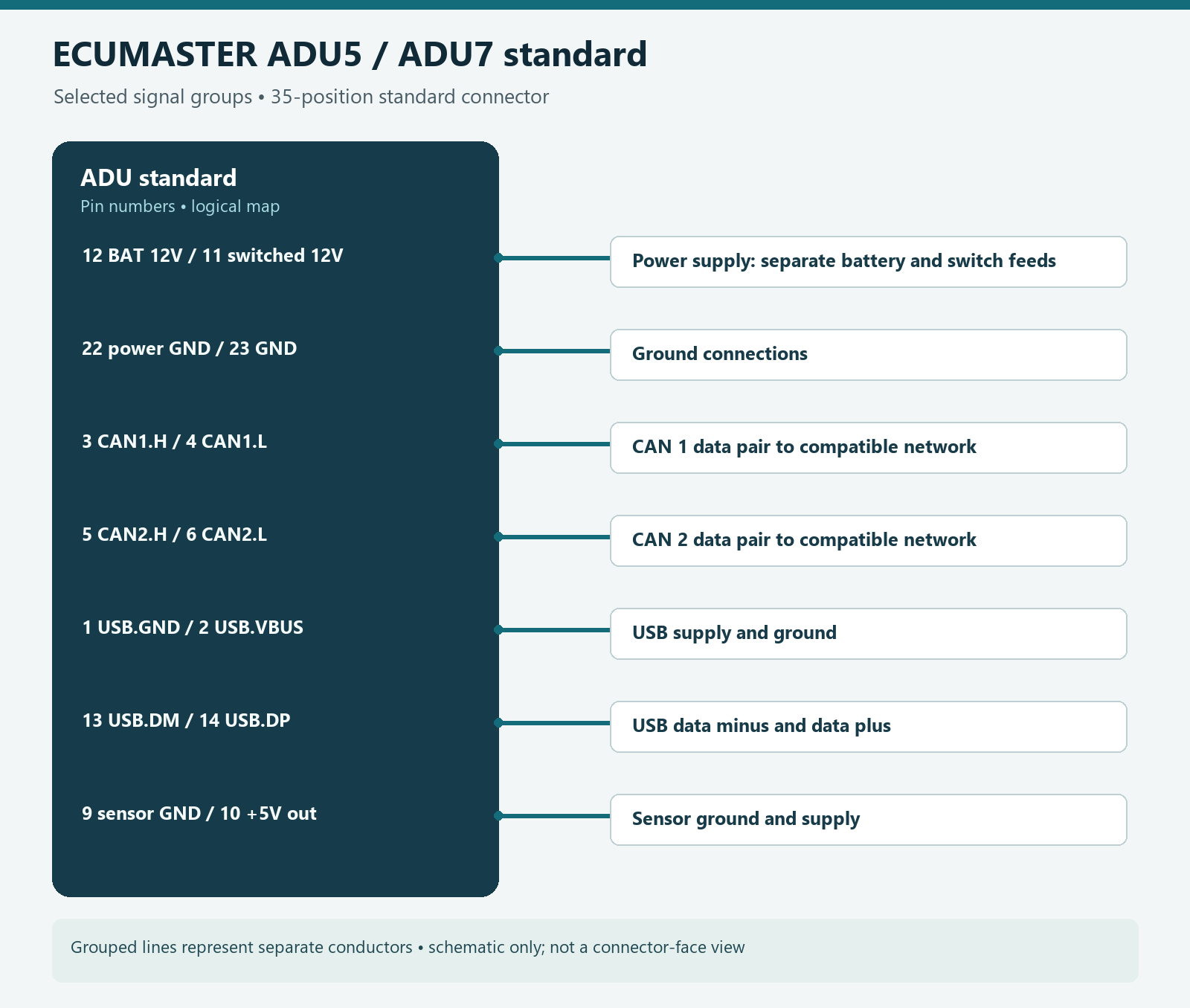
The standard ADU uses the 35-position AMP automotive connector. The illustration shows the device's rear connector as labelled by the manufacturer. Verify the connector and view before wiring; the 37-position Autosport pinout is different. Source: ECUMASTER standard ADU pinout.
| Pin | Function |
|---|---|
| 1 | USB.GND |
| 2 | USB.VBUS |
| 3 | CAN1.H |
| 4 | CAN1.L |
| 5 | CAN2.H |
| 6 | CAN2.L |
| 7 | RS232.RXD |
| 8 | RS232.TXD |
| 9 | Sensor ground |
| 10 | +5V output |
| 11 | Switched 12V |
| 12 | Battery 12V |
| 13 | USB.DM |
| 14 | USB.DP |
| 15 | Analog in A5 |
| 16 | Analog in A3 |
| 17 | Analog in A1 |
| 18 | Frequency/digital in D8 |
| 19 | Frequency/digital in D6 |
| 20 | Frequency/digital in D4 |
| 21 | Frequency/digital in D2 |
| 22 | Power ground |
| 23 | Ground |
| 24 | Analog in A8 |
| 25 | Analog in A7 |
| 26 | Analog in A6 |
| 27 | Analog in A4 |
| 28 | Analog in A2 |
| 29 | Analog output |
| 30 | Frequency/digital in D7 |
| 31 | Frequency/digital in D5 |
| 32 | Frequency/digital in D3 |
| 33 | Frequency/digital in D1 |
| 34 | Aux 1 |
| 35 | Aux 2 |
Wiring and commissioning
The schematic groups separate conductors; consult the full source before making a harness. Battery, switched supply and power ground are pins 12, 11 and 22 respectively; CAN1 high/low are 3/4. USB requires VBUS 2, ground 1, data minus 13 and data plus 14 on the matching receptacle. Sensor inputs, grounds and +5 V output have distinct limits; follow the ADU manual and exact ECU guide. With power isolated, verify cavity numbers and continuity; then configure channels and test a short recording.
Manufacturer overview: ECUMASTER dataloggers and displays. Confirm revision, loom, connector and options before installation.