MoTeC L120 USB (MoTeC part #18045) is an enclosed motorsport data logger without an integrated driver display. The information here is specific to the cited part; check the label, hardware revision, options and vehicle protocol before connection.

Specifications and options
- Enclosed logger without an integrated display; #18045 includes 120 MB internal recording and USB logging.
- Two configurable CAN buses and RS232; analogue voltage, temperature and auxiliary functions require the I/O upgrade.
- Manufacturer specifies rates up to 500 samples per second, 6–32 V DC operation and a three-axis accelerometer; T2 telemetry requires an upgrade and a separate link.
Connector and pinout
34-way (mating connector #65044): the table below follows the manufacturer’s pinout for part #18045. Check cavity numbering and the manufacturer's connector view; the functional map is not a physical connector-face drawing. Blank cells retain the source's unspecified function; do not assign them by assumption. Inputs marked as optional need the appropriate enabled upgrade.
| Pin | Name | Standard function | Optional function |
|---|---|---|---|
| 1 | E-TX– | Ethernet Transmit – | |
| 2 | E-TX+ | Ethernet Transmit + | |
| 3 | AV1 | Analogue Voltage Input 1 | |
| 4 | AV2 | Analogue Voltage Input 2 | |
| 5 | AV3 | Analogue Voltage Input 3 | |
| 6 | AV4 | Analogue Voltage Input 4 | |
| 7 | 8V | Sensor 8 V | |
| 8 | 5V | Sensor 5 V | |
| 9 | 0V | Sensor 0 V | |
| 10 | E-RX– | Ethernet Receive – | |
| 11 | E-RX+ | Ethernet Receive + | |
| 12 | AV5 | Analogue Voltage Input 5 | |
| 13 | AV6 | Analogue Voltage Input 6 | |
| 14 | DIG1 | Digital Input 1 | |
| 15 | DIG2 | Digital Input 2 | |
| 16 | AT1 | Analogue Temp Input 1 | |
| 17 | AT2 | Analogue Temp Input 2 | |
| 18 | CAN1L | CAN1 Lo | |
| 19 | CAN1H | CAN1 Hi | |
| 20 | RS232-1 TX | RS232-1 Transmit Output | |
| 21 | SPD1 | Speed Input 1 | |
| 22 | SPD2 | Speed Input 2 | |
| 23 | SPD3 | Speed Input 3 | |
| 24 | Not used | Not used | |
| 25 | RS232-2 RX | RS232-2 Receive Input | |
| 26 | CAN2L | CAN2 Lo / RS232 Ground Input | |
| 27 | CAN2H | CAN2 Hi / RS232 Receive Input | |
| 28 | RS232-1 RX | RS232-1 Receive Input | |
| 29 | AUX1 | Auxiliary Output 1 | |
| 30 | AUX2 | Auxiliary Output 2 | |
| 31 | AUX3 | Auxiliary Output 3 | |
| 32 | AUX4 | Auxiliary Output 4 | |
| 33 | BAT+ | Battery Positive | |
| 34 | BAT– | Battery Negative |
Wiring and configuration
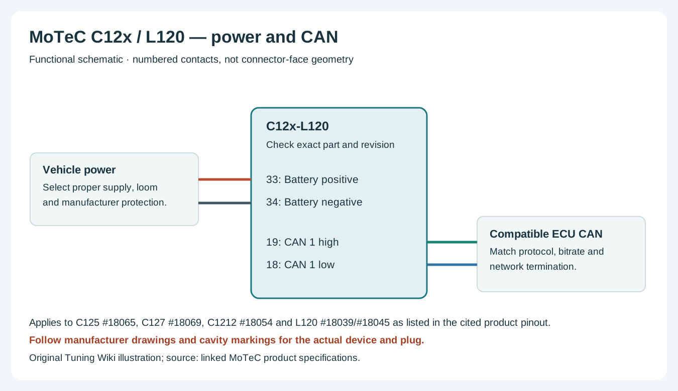
Use the correct connector, power and sensor return for this unit. Match CAN high and low to a compatible, correctly configured network and check existing termination. ECU channels, sensors and lap timing depend on the specific hardware, protocol, configuration and licensed options. Use manufacturer instructions for wire gauge, supply protection and continuity checks; do not connect vehicle battery voltage to a sensor reference output.
MoTeC i2 supports reviewing recorded data; Pro analysis and T2 telemetry require the applicable upgrades. A telemetry licence alone does not provide a radio or cellular connection. See the MoTeC manufacturer guide for family comparisons and references.
Data analysis software

The L120 USB records data for later analysis; the exact memory, logging and Pro Analysis options depend on the unit and licence. MoTeC i2 reviews recorded channels in graphs and reports; i2 Pro features depend on the device upgrade or applicable software licence. See the manufacturer model and analysis comparison and i2 software and licence information.
Retrieve a recording with the compatible MoTeC device manager, then open it in i2 to compare channels and laps when suitable position data has been recorded. Download MoTeC software from the official downloads library; see the MoTeC manufacturer guide for the Standard and Pro options.