EVO6L is a standalone sensor and ECU logger with individual Binder sockets. It has a different connector layout from EVO6. For the range overview see AiM in-car dataloggers.

Specifications
| Item | Specification |
|---|---|
| ECU | CAN, RS232 or K-Line |
| Inputs | Five configurable analogue inputs; two speed inputs and coil RPM |
| Inertial / GPS | Three-axis accelerometer and gyro; GPS09c module |
| Storage | 4 GB internal |
| Outputs / connectors | One digital output, up to 1 A; thirteen Binder 712 connectors; IP65 |
Specifications and kit contents: AiM AiM EVO6L technical documentation. Check hardware generation and exact kit.
Pinout
The AiM technical sheet labels each female Binder 712 connector from the external device view. The 7-pin ECU socket is CAN1+ / CAN1− / 9–15 V input / RS232 TX / RS232 RX / K-Line / battery ground in pins 1–7. EXP and GPS are five-pin: CAN+ / ground / +Vbout CAN / CAN− / +Vbext CAN.
| EVO6L connector | Pin assignments |
|---|---|
| POWER, 2-pin | 1: 9–15 V power in; 2: battery ground |
| CH1–CH5, each 4-pin | 1: corresponding analogue input; 2: analogue ground; 3: +Vbout; 4: Vref |
| Speed, 4-pin | 1: speed 1; 2: ground; 3: +Vbout; 4: speed 2 |
| Beacon, 4-pin | 1: magnetic lap; 2: ground; 3: +Vbout; 4: optical lap |
| RPM/Dout, 5-pin | 1: RPM; 2: PGND; 3 and 4: not connected; 5: digital output |
| USB, 3-pin | 1: USB D+; 2: USB D−; 3: ground |
Wiring and installation
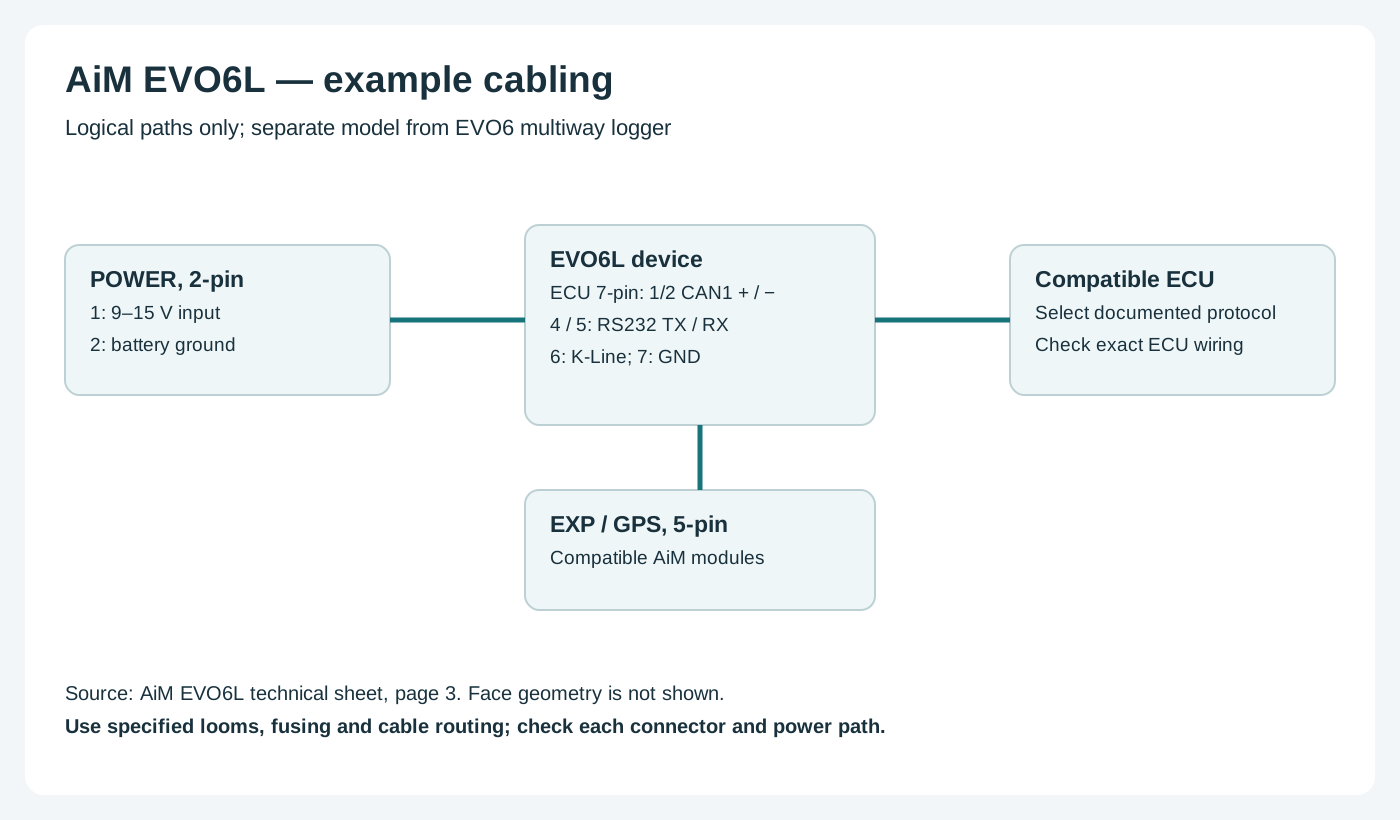
AiM's kit list identifies CAN or OBD-II leads, GPS09c, power and USB cables. Sensors on CH1–CH5 require correctly rated and configured inputs; the RPM/output lead is separate. Check the kit and power arrangement before combining cables.
Choose the correct model-specific lead and configure the ECU protocol in Race Studio 3. A connector shape alone does not establish vehicle compatibility. Confirm every cavity number, signal level, ground, power source and electrical limit in the linked AiM documentation before wiring; diagrams are from the device view or a conceptual schematic as stated. Secure the loom and make connections with power disconnected.
Software and further reading
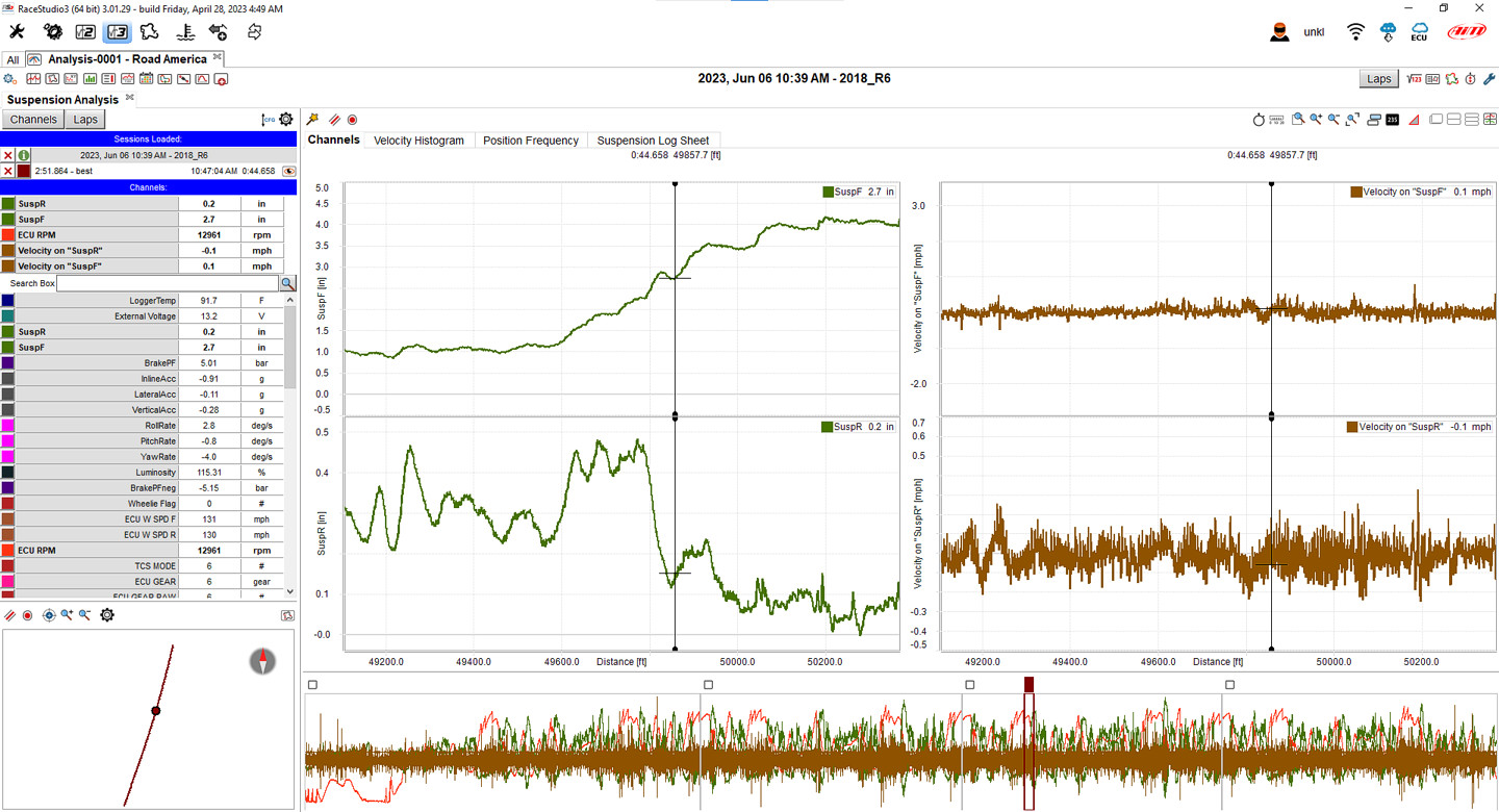
Analysis and download: AiM supports PC analysis of EVO6L recordings in Race Studio Analysis. EVO6L and EVO6 differ in their connections; consult the model guide for the download method. AiM model guidance. Download the Windows software from AiM Race Studio 3 software downloads. For capabilities and compatibility see AiM data-log analysis software.
Use AiM Race Studio 3 to configure supported devices and analyse recorded sessions. Check the specific ECU protocol and cable before connection; not every source exposes every channel. Manufacturer references: model documentation; product and installation guidance.