Removed text is struck through; added text is highlighted.
Precision DynoTech supplies water-brake dyno equipment and DC-series Dyno Data Systems with its RevBench software. The maker describes applications including engine and chassis dynos, DIY installations and upgrades from older Stuska analogue gauges. Compatibility depends on the actual sensor and brake arrangement. Manufacturer overview.
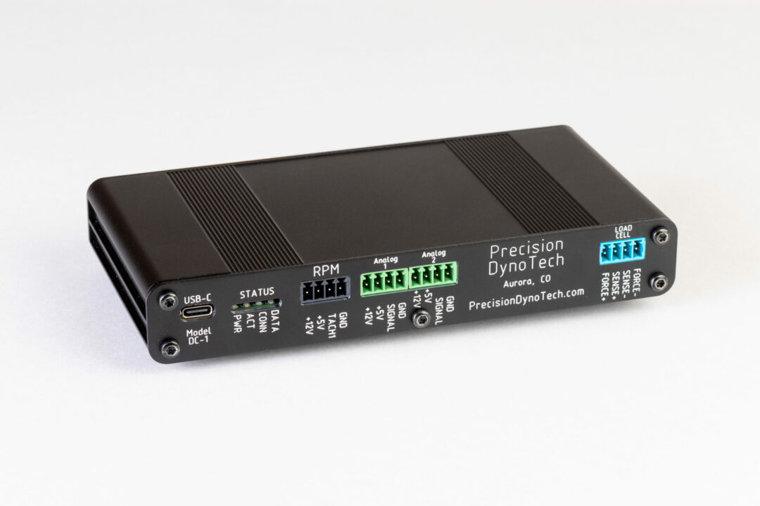
Precision DynoTech DC-1 data-acquisition unit. Photo: Precision DynoTech, used with permission.
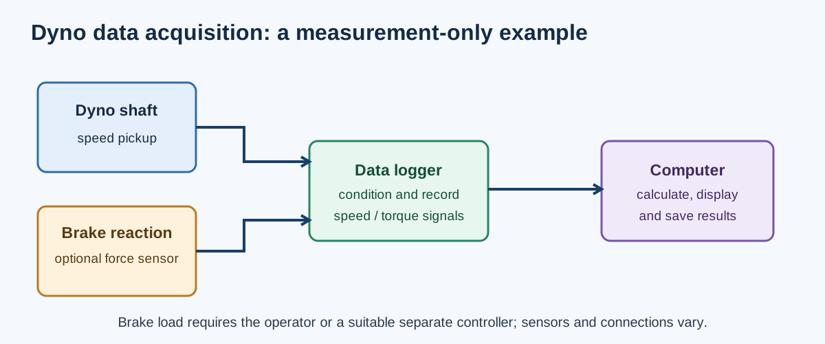
Illustrative measurement-only arrangement: optional brake loading needs the operator or a separate suitable controller. Sensor interfaces and layouts vary. Original schematic for Tuning Wiki, CC BY 4.0.
DC-series models
ModelManufacturer-listed hardware and useDC-1One RPM input, one bridge-type load-cell input and two analogue inputs, with USB-C and RevBench. Intended for simpler data logging; the cited listing does not include electronic brake control.DC-2Builds on DC-1 with two thermocouple inputs and a built-in weather station according to the maker. The listing describes a simpler acquisition system without the DC-3's electronic brake-control features.DC-3Lists two RPM inputs, two load-cell inputs, four analogue inputs, four K-type thermocouples, CAN and weather sensing. Its stepper command can connect to a suitable stepper driver and motor for a load valve; an auxiliary PWM output can command a compatible eddy-current brake power supply.
The DC-3 outputs are control interfaces, not a complete universal brake driver. The actual valve, stepper drive, power supply, sensor signals and interlocks must match the dyno. Do not infer the number of independently controlled brakes, automatic RPM modes or compatible CAN devices from socket count alone. Ask the supplier for the version and installed configuration.
RevBench and brake control
RevBench records and displays data from the maker's DC systems, with graph/table views, test runs and correction options. The software release notes describe later stepper-control and PID-loop changes and an inertia mode; availability and operation depend on the hardware and software generation. The downloads page contains inconsistent version and installer labels, so confirm the actual version and features with the supplier.
The measurement diagram above represents DC-1/DC-2 style data capture. A speed-hold feedback loop such as the one below requires the appropriate DC-3 control setup, driver, actuator, compatible software and calibration; it is not evidence that every DC-series unit controls a brake.
Generic speed-hold feedback loop; actual DC-3 capabilities depend on software and compatible external equipment. Original schematic for Tuning Wiki, CC BY 4.0.
Installation and comparison
Check sensor type and pulse count, load-cell rating and calibration, weather and analogue inputs, valve or coil-driver compatibility, data acquisition mode and control features with the supplier. An older dyno may need additional sensors, actuators or installation work. See dynamometer control systems and factory and aftermarket controller comparison.
Rendered revisions
Open each version to inspect formatting, tables and photographs.
Revision 1: Precision DynoTech dynamometer data systems
Precision DynoTech supplies water-brake dyno equipment and DC-series Dyno Data Systems with its RevBench software. The maker describes applications including engine and chassis dynos, DIY installations and upgrades from older Stuska analogue gauges. Compatibility depends on the actual sensor and brake arrangement. Manufacturer overview.
Precision DynoTech DC-1 data-acquisition unit. Photo: Precision DynoTech, used with permission.Illustrative measurement-only arrangement: optional brake loading needs the operator or a separate suitable controller. Sensor interfaces and layouts vary. Original schematic for Tuning Wiki, CC BY 4.0.
One RPM input, one bridge-type load-cell input and two analogue inputs, with USB-C and RevBench. Intended for simpler data logging; the cited listing does not include electronic brake control.
Builds on DC-1 with two thermocouple inputs and a built-in weather station according to the maker. The listing describes a simpler acquisition system without the DC-3's electronic brake-control features.
Lists two RPM inputs, two load-cell inputs, four analogue inputs, four K-type thermocouples, CAN and weather sensing. Its stepper command can connect to a suitable stepper driver and motor for a load valve; an auxiliary PWM output can command a compatible eddy-current brake power supply.
The DC-3 outputs are control interfaces, not a complete universal brake driver. The actual valve, stepper drive, power supply, sensor signals and interlocks must match the dyno. Do not infer the number of independently controlled brakes, automatic RPM modes or compatible CAN devices from socket count alone. Ask the supplier for the version and installed configuration.
RevBench and brake control
RevBench records and displays data from the maker's DC systems, with graph/table views, test runs and correction options. The software release notes describe later stepper-control and PID-loop changes and an inertia mode; availability and operation depend on the hardware and software generation. The downloads page contains inconsistent version and installer labels, so confirm the actual version and features with the supplier.
The measurement diagram above represents DC-1/DC-2 style data capture. A speed-hold feedback loop such as the one below requires the appropriate DC-3 control setup, driver, actuator, compatible software and calibration; it is not evidence that every DC-series unit controls a brake.
Generic speed-hold feedback loop; actual DC-3 capabilities depend on software and compatible external equipment. Original schematic for Tuning Wiki, CC BY 4.0.
Installation and comparison
Check sensor type and pulse count, load-cell rating and calibration, weather and analogue inputs, valve or coil-driver compatibility, data acquisition mode and control features with the supplier. An older dyno may need additional sensors, actuators or installation work. See dynamometer control systems and factory and aftermarket controller comparison.
Revision 1: Precision DynoTech dynamometer data systems
Precision DynoTech supplies water-brake dyno equipment and DC-series Dyno Data Systems with its RevBench software. The maker describes applications including engine and chassis dynos, DIY installations and upgrades from older Stuska analogue gauges. Compatibility depends on the actual sensor and brake arrangement. Manufacturer overview.
Precision DynoTech DC-1 data-acquisition unit. Photo: Precision DynoTech, used with permission.Illustrative measurement-only arrangement: optional brake loading needs the operator or a separate suitable controller. Sensor interfaces and layouts vary. Original schematic for Tuning Wiki, CC BY 4.0.
One RPM input, one bridge-type load-cell input and two analogue inputs, with USB-C and RevBench. Intended for simpler data logging; the cited listing does not include electronic brake control.
Builds on DC-1 with two thermocouple inputs and a built-in weather station according to the maker. The listing describes a simpler acquisition system without the DC-3's electronic brake-control features.
Lists two RPM inputs, two load-cell inputs, four analogue inputs, four K-type thermocouples, CAN and weather sensing. Its stepper command can connect to a suitable stepper driver and motor for a load valve; an auxiliary PWM output can command a compatible eddy-current brake power supply.
The DC-3 outputs are control interfaces, not a complete universal brake driver. The actual valve, stepper drive, power supply, sensor signals and interlocks must match the dyno. Do not infer the number of independently controlled brakes, automatic RPM modes or compatible CAN devices from socket count alone. Ask the supplier for the version and installed configuration.
RevBench and brake control
RevBench records and displays data from the maker's DC systems, with graph/table views, test runs and correction options. The software release notes describe later stepper-control and PID-loop changes and an inertia mode; availability and operation depend on the hardware and software generation. The downloads page contains inconsistent version and installer labels, so confirm the actual version and features with the supplier.
The measurement diagram above represents DC-1/DC-2 style data capture. A speed-hold feedback loop such as the one below requires the appropriate DC-3 control setup, driver, actuator, compatible software and calibration; it is not evidence that every DC-series unit controls a brake.
Generic speed-hold feedback loop; actual DC-3 capabilities depend on software and compatible external equipment. Original schematic for Tuning Wiki, CC BY 4.0.
Installation and comparison
Check sensor type and pulse count, load-cell rating and calibration, weather and analogue inputs, valve or coil-driver compatibility, data acquisition mode and control features with the supplier. An older dyno may need additional sensors, actuators or installation work. See dynamometer control systems and factory and aftermarket controller comparison.