Removed text is struck through; added text is highlighted.
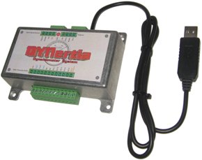
DTec DYNertia is a USB dynamometer measurement system and DYNertia3 Windows software for inertia and manually loaded brake dynos. DTec describes it for home-built or upgraded engine and chassis installations, including kart, motorcycle, car and model-engine testing. DTec product page.
DYNertia acquisition unit shown by the manufacturer. Photo: DTec, used with permission.
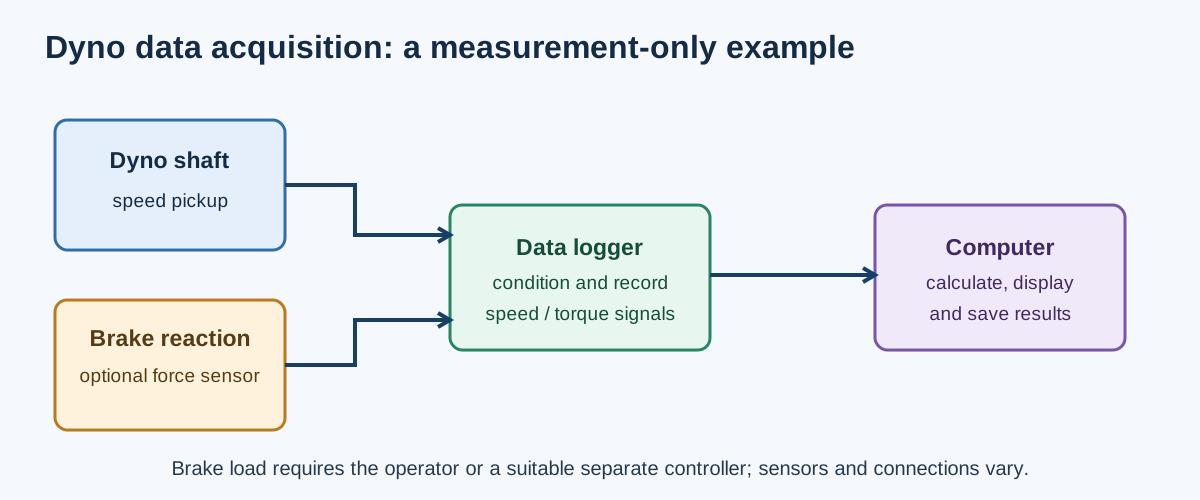
Illustrative measurement-only arrangement: optional brake loading needs the operator or a separate suitable controller. Sensor interfaces and layouts vary. Original schematic for Tuning Wiki, CC BY 4.0.
How it measures
The DYNertia hardware uses a shaft-speed sensor and a PC over USB. The published kit includes a Hall-effect sensor and trigger magnet. On an inertia dyno, the software calculates power from speed and the configured rotating inertia. On a brake dyno it can use a properly conditioned load-cell, pressure-sensor or other compatible torque signal. Manufacturer documentation lists five analogue and one digital input, plus calculated channels; applicable accessories and sensor conditioning must be specified. DYNertia3 manual; DTec load-cell amplifier.
Brake compatibility and limitation
DTec describes measurement on water, eddy-current, hydraulic and friction brake dynos. This is instrumentation compatibility subject to the speed and force signals, not a claim that the software drives those absorbers. DYNertia3 does not automatically vary brake load or hold an entered RPM. The operator adjusts the brake or a separate suitable control system must do so. The manufacturer calls this an open-loop brake arrangement. Brake-dyno quick start.
Software and options
DYNertia3 records and graphs results, overlays runs, handles user-selected atmospheric corrections and can use a learned or entered gear ratio when configuring engine RPM from the measured shaft. DTec lists optional RPM and weather interfaces; analogue sensors such as wideband lambda or thermocouples may require their own compatible signal conditioners. The manual explains filtering, sensor scaling and separate engine-speed input. A calculated correction or loss estimate must be reported as such, rather than as direct crankshaft measurement.
Specifying a conversion
Check the sensor and trigger mounting, shaft speed range, configured inertia or gear ratio, load-cell amplifier and calibration, additional signal conditioning and Windows/USB compatibility. Ensure the separate brake control and its safety arrangements are suitable for the machine. A correctly calibrated logger does not increase absorber capacity or add closed-loop speed holding. See dynamometer control systems and the controller comparison.
Rendered revisions
Open each version to inspect formatting, tables and photographs.
Revision 1: DTec DYNertia dynamometer systems
DTec DYNertia is a USB dynamometer measurement system and DYNertia3 Windows software for inertia and manually loaded brake dynos. DTec describes it for home-built or upgraded engine and chassis installations, including kart, motorcycle, car and model-engine testing. DTec product page.
DYNertia acquisition unit shown by the manufacturer. Photo: DTec, used with permission.Illustrative measurement-only arrangement: optional brake loading needs the operator or a separate suitable controller. Sensor interfaces and layouts vary. Original schematic for Tuning Wiki, CC BY 4.0.
How it measures
The DYNertia hardware uses a shaft-speed sensor and a PC over USB. The published kit includes a Hall-effect sensor and trigger magnet. On an inertia dyno, the software calculates power from speed and the configured rotating inertia. On a brake dyno it can use a properly conditioned load-cell, pressure-sensor or other compatible torque signal. Manufacturer documentation lists five analogue and one digital input, plus calculated channels; applicable accessories and sensor conditioning must be specified. DYNertia3 manual; DTec load-cell amplifier.
Brake compatibility and limitation
DTec describes measurement on water, eddy-current, hydraulic and friction brake dynos. This is instrumentation compatibility subject to the speed and force signals, not a claim that the software drives those absorbers. DYNertia3 does not automatically vary brake load or hold an entered RPM. The operator adjusts the brake or a separate suitable control system must do so. The manufacturer calls this an open-loop brake arrangement. Brake-dyno quick start.
Software and options
DYNertia3 records and graphs results, overlays runs, handles user-selected atmospheric corrections and can use a learned or entered gear ratio when configuring engine RPM from the measured shaft. DTec lists optional RPM and weather interfaces; analogue sensors such as wideband lambda or thermocouples may require their own compatible signal conditioners. The manual explains filtering, sensor scaling and separate engine-speed input. A calculated correction or loss estimate must be reported as such, rather than as direct crankshaft measurement.
Specifying a conversion
Check the sensor and trigger mounting, shaft speed range, configured inertia or gear ratio, load-cell amplifier and calibration, additional signal conditioning and Windows/USB compatibility. Ensure the separate brake control and its safety arrangements are suitable for the machine. A correctly calibrated logger does not increase absorber capacity or add closed-loop speed holding. See dynamometer control systems and the controller comparison.
Revision 1: DTec DYNertia dynamometer systems
DTec DYNertia is a USB dynamometer measurement system and DYNertia3 Windows software for inertia and manually loaded brake dynos. DTec describes it for home-built or upgraded engine and chassis installations, including kart, motorcycle, car and model-engine testing. DTec product page.
DYNertia acquisition unit shown by the manufacturer. Photo: DTec, used with permission.Illustrative measurement-only arrangement: optional brake loading needs the operator or a separate suitable controller. Sensor interfaces and layouts vary. Original schematic for Tuning Wiki, CC BY 4.0.
How it measures
The DYNertia hardware uses a shaft-speed sensor and a PC over USB. The published kit includes a Hall-effect sensor and trigger magnet. On an inertia dyno, the software calculates power from speed and the configured rotating inertia. On a brake dyno it can use a properly conditioned load-cell, pressure-sensor or other compatible torque signal. Manufacturer documentation lists five analogue and one digital input, plus calculated channels; applicable accessories and sensor conditioning must be specified. DYNertia3 manual; DTec load-cell amplifier.
Brake compatibility and limitation
DTec describes measurement on water, eddy-current, hydraulic and friction brake dynos. This is instrumentation compatibility subject to the speed and force signals, not a claim that the software drives those absorbers. DYNertia3 does not automatically vary brake load or hold an entered RPM. The operator adjusts the brake or a separate suitable control system must do so. The manufacturer calls this an open-loop brake arrangement. Brake-dyno quick start.
Software and options
DYNertia3 records and graphs results, overlays runs, handles user-selected atmospheric corrections and can use a learned or entered gear ratio when configuring engine RPM from the measured shaft. DTec lists optional RPM and weather interfaces; analogue sensors such as wideband lambda or thermocouples may require their own compatible signal conditioners. The manual explains filtering, sensor scaling and separate engine-speed input. A calculated correction or loss estimate must be reported as such, rather than as direct crankshaft measurement.
Specifying a conversion
Check the sensor and trigger mounting, shaft speed range, configured inertia or gear ratio, load-cell amplifier and calibration, additional signal conditioning and Windows/USB compatibility. Ensure the separate brake control and its safety arrangements are suitable for the machine. A correctly calibrated logger does not increase absorber capacity or add closed-loop speed holding. See dynamometer control systems and the controller comparison.