Removed text is struck through; added text is highlighted.
PnPduino Toyota 1FZ-FE Gen2 is a PnPduino programmable engine-management ECU. Manufacturer product information.
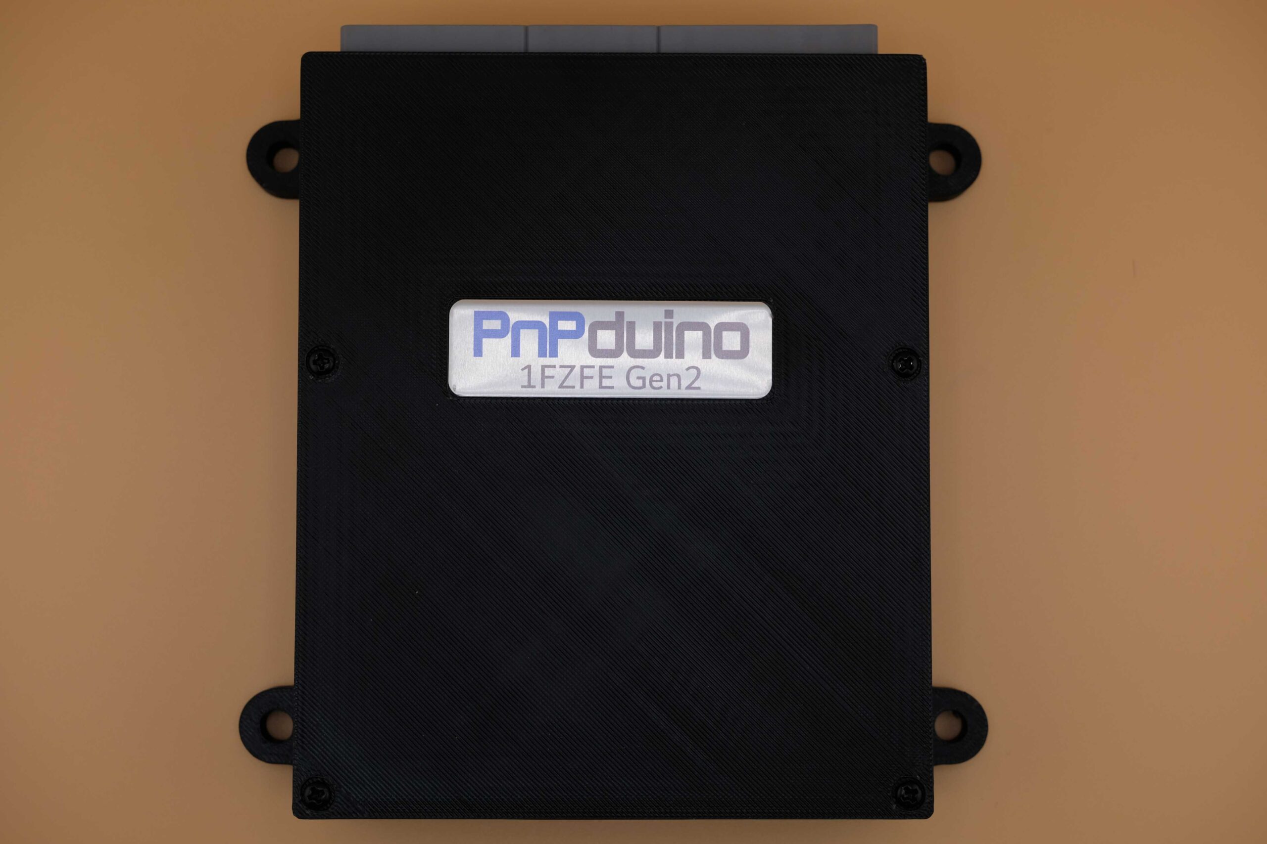
PnPduino Toyota 1FZ-FE Gen2. PnPduino manufacturer product photograph, reproduced with permission.
Application and identification
Plug-in for the manufacturer's 1998–2002 4.5-litre Toyota Land Cruiser 1FZ-FE Gen2 application, manual transmission only. It uses three vehicle plugs of 26, 16 and 22 positions. The supplier explicitly says Gen2 and Gen3 pinouts differ and must not be interchanged.
System and wiring
A VR conditioner is fitted. The manufacturer describes semi-sequential injection and wasted-spark ignition, stock MAP sensing, and high- or low-impedance injector support. An aftermarket wideband controller is required for proper tuning.
Connector identification
ConnectorManufacturer descriptionScopeVehicle connector 126 positionsSee manufacturer for matching Gen2 cavity assignmentsVehicle connector 216 positionsSee manufacturer for matching Gen2 cavity assignmentsVehicle connector 322 positionsSee manufacturer for matching Gen2 cavity assignments
The manufacturer’s numbered Gulf-region connector schedules are transcribed below. C3 is shown on the diagram but not identified in its source table, and B2 and B16 share a source row; check the exact loom and manufacturer diagram.A complete pin-by-pin ECU connector table has not been verified from the cited product information. Obtain the diagram for the exact model and revision from PnPduino documentation; the vehicle ECU pinout and other PnPduino models must not be assumed interchangeable.
Software and calibration
This listing specifies official Speeduino firmware and use of the SpeedyLoader INI; check the actual build and manufacturer guidance. A supplied base map needs final tuning.
See the PnPduino manufacturer index.
Manufacturer connector assignmentsThe source labels this diagram for Gulf-country 1FZ-FE Gen2 and views the front of the male ECU connector. Its labels and model-specific hardware differ from the other generation. B2 and B16 share one source row; C3 is pictured but is absent from the source table and is marked accordingly here. Original-vehicle labels, PnPduino assignments and TunerStudio pin numbers are different columns; do not treat an OEM label as evidence of an active ECU connection. Source: PnPduino 1FZ-FE Gen2 pinout. Blank cells reflect the original schedule, not a declaration that the position is spare. The original uses colour to distinguish retained vehicle, unused vehicle and added PnPduino signals; check the original drawing and exact regional loom before wiring.Connector BECU pin1FZ label1FZ descriptionPnPduino connectionPnPduino functionTunerStudio pinRemarksB13E01Power GroundB26E02Power GroundB12INJ1/5Injector 1 and 5INJ1Injector 18B25INJ3/6Injector 3 and 6INJ2Injector 27B11INJ2/4Injector 2 and 4INJ3Injector 36B24INJ4Injector 45B10RSDRotary ISCVIDLE1Idle 19B23IMOImmobilizerB9FANRadiator Fan24Not used by defaultB22LC3Low Current 328B8TACHTachometer OutputTACHTachometer Output22B21LC2Low Current 227B7B20IGT1Igniter 1 and 5IG1Ignition 135B6IG4Ignition 434Not used by defaultB19IGT2Igniter 3 and 6IG2Ignition 236B5G2CAM signalVR2+VR2+18from CAM SensorB18IGT3Igniter 2 and 4IG3Ignition 333B4NE+CRANK signalVR1+VR1+19from CRANK SensorB17NE-CAM/CRANK GroundVR1-VR1-B3IGFIgnition ConfirmationB2 & B1612VFFused 12VOnly for 12V SensorsB15GRNDSensor GroundOnly for 12V SensorsB1IDLE2Idle 210Can be used for High OutputB14E1Engine GroundConnector AECU pin1FZ label1FZ descriptionPnPduino connectionPnPduino functionTunerStudio pinRemarksA8TCData LinkA16VVTVVT11Can be used for High OutputA7VAFVariable ResistorA15FPRFuel Pump ResistorA6CANLCAN LoIf STM32 is usedA14CANHCAN HiIf STM32 is usedA5KNKLKnock Sensor LeftKNOCKKnock21Not used by default, for future useA13KNKRKnock Sensor RightFLEXFlex sensor2Not used by defaultA4THWCoolant TemperatureCLTEngine Coolant TempA4A12IMIImmobilizerA3THAIntake Air TemperatureIATIntake Air TempA5A11VTAThrottle Position SensorTPSThrottle Position SensorA3A2PIMMAP sensorMAPMAP sensorA0A10SILData LinkA1VC5V Sensor Supply5V5V from ECUFused 5V to sensorsA9E2Sensor GroundConnector CECU pin1FZ label1FZ descriptionPnPduino connectionPnPduino functionTunerStudio pinRemarksC11STAStarter SwitchC22NSWNeutral SwitchCLUTCHClutch switch37C10A/C1AC AmplifierINP2Input 2A9AC Switch to Idle UpC21ACTAC ControlC9SPDVehicle SpeedVSSVehicle Speed20C20INP3Input 3A10C8FPM1Main Fuel PumpC19FPM2Sub Fuel PumpC7FPMSFuel Tank Change SwitchINP6Input 6A12C18INP5Input 5A6C6INP1Input 1A8C17INP4Input 4A11C5WCheck Engine LightFAN2Fan 225Not used by default, for future useC16FPRFuel Pump ResistorINP7Input 7A13C4FCCircuit Opening RelayFPFuel Pump23C15FPR2Sub Fuel Pump RelayLC1Low Current 126C14FPLDSub Fuel Indicator LampLC4Low Current 429C3Position C3 is not listed in the manufacturer tableC2STPStop LightC13BOOSTBoost12Can be used for High OutputC1BATTBattery Constant 12VNot used by defaultC12+BIgnition +12V switchedShould be fused 12V supply to ECU
Rendered revisions
Open each version to inspect formatting, tables and photographs.
Plug-in for the manufacturer's 1998–2002 4.5-litre Toyota Land Cruiser 1FZ-FE Gen2 application, manual transmission only. It uses three vehicle plugs of 26, 16 and 22 positions. The supplier explicitly says Gen2 and Gen3 pinouts differ and must not be interchanged.
System and wiring
A VR conditioner is fitted. The manufacturer describes semi-sequential injection and wasted-spark ignition, stock MAP sensing, and high- or low-impedance injector support. An aftermarket wideband controller is required for proper tuning.
Connector identification
Connector
Manufacturer description
Scope
Vehicle connector 1
26 positions
See manufacturer for matching Gen2 cavity assignments
Vehicle connector 2
16 positions
See manufacturer for matching Gen2 cavity assignments
Vehicle connector 3
22 positions
See manufacturer for matching Gen2 cavity assignments
A complete pin-by-pin ECU connector table has not been verified from the cited product information. Obtain the diagram for the exact model and revision from PnPduino documentation; the vehicle ECU pinout and other PnPduino models must not be assumed interchangeable.
Software and calibration
This listing specifies official Speeduino firmware and use of the SpeedyLoader INI; check the actual build and manufacturer guidance. A supplied base map needs final tuning.
Plug-in for the manufacturer's 1998–2002 4.5-litre Toyota Land Cruiser 1FZ-FE Gen2 application, manual transmission only. It uses three vehicle plugs of 26, 16 and 22 positions. The supplier explicitly says Gen2 and Gen3 pinouts differ and must not be interchanged.
System and wiring
A VR conditioner is fitted. The manufacturer describes semi-sequential injection and wasted-spark ignition, stock MAP sensing, and high- or low-impedance injector support. An aftermarket wideband controller is required for proper tuning.
Connector identification
Connector
Manufacturer description
Scope
Vehicle connector 1
26 positions
See manufacturer for matching Gen2 cavity assignments
Vehicle connector 2
16 positions
See manufacturer for matching Gen2 cavity assignments
Vehicle connector 3
22 positions
See manufacturer for matching Gen2 cavity assignments
The manufacturer’s numbered Gulf-region connector schedules are transcribed below. C3 is shown on the diagram but not identified in its source table, and B2 and B16 share a source row; check the exact loom and manufacturer diagram.
Software and calibration
This listing specifies official Speeduino firmware and use of the SpeedyLoader INI; check the actual build and manufacturer guidance. A supplied base map needs final tuning.
The source labels this diagram for Gulf-country 1FZ-FE Gen2 and views the front of the male ECU connector. Its labels and model-specific hardware differ from the other generation. B2 and B16 share one source row; C3 is pictured but is absent from the source table and is marked accordingly here. Original-vehicle labels, PnPduino assignments and TunerStudio pin numbers are different columns; do not treat an OEM label as evidence of an active ECU connection. Source: PnPduino 1FZ-FE Gen2 pinout. Blank cells reflect the original schedule, not a declaration that the position is spare. The original uses colour to distinguish retained vehicle, unused vehicle and added PnPduino signals; check the original drawing and exact regional loom before wiring.
Connector B
ECU pin
1FZ label
1FZ description
PnPduino connection
PnPduino function
TunerStudio pin
Remarks
B13
E01
Power Ground
B26
E02
Power Ground
B12
INJ1/5
Injector 1 and 5
INJ1
Injector 1
8
B25
INJ3/6
Injector 3 and 6
INJ2
Injector 2
7
B11
INJ2/4
Injector 2 and 4
INJ3
Injector 3
6
B24
INJ4
Injector 4
5
B10
RSD
Rotary ISCV
IDLE1
Idle 1
9
B23
IMO
Immobilizer
B9
FAN
Radiator Fan
24
Not used by default
B22
LC3
Low Current 3
28
B8
TACH
Tachometer Output
TACH
Tachometer Output
22
B21
LC2
Low Current 2
27
B7
B20
IGT1
Igniter 1 and 5
IG1
Ignition 1
35
B6
IG4
Ignition 4
34
Not used by default
B19
IGT2
Igniter 3 and 6
IG2
Ignition 2
36
B5
G2
CAM signal
VR2+
VR2+
18
from CAM Sensor
B18
IGT3
Igniter 2 and 4
IG3
Ignition 3
33
B4
NE+
CRANK signal
VR1+
VR1+
19
from CRANK Sensor
B17
NE-
CAM/CRANK Ground
VR1-
VR1-
B3
IGF
Ignition Confirmation
B2 & B16
12VF
Fused 12V
Only for 12V Sensors
B15
GRND
Sensor Ground
Only for 12V Sensors
B1
IDLE2
Idle 2
10
Can be used for High Output
B14
E1
Engine Ground
Connector A
ECU pin
1FZ label
1FZ description
PnPduino connection
PnPduino function
TunerStudio pin
Remarks
A8
TC
Data Link
A16
VVT
VVT
11
Can be used for High Output
A7
VAF
Variable Resistor
A15
FPR
Fuel Pump Resistor
A6
CANL
CAN Lo
If STM32 is used
A14
CANH
CAN Hi
If STM32 is used
A5
KNKL
Knock Sensor Left
KNOCK
Knock
21
Not used by default, for future use
A13
KNKR
Knock Sensor Right
FLEX
Flex sensor
2
Not used by default
A4
THW
Coolant Temperature
CLT
Engine Coolant Temp
A4
A12
IMI
Immobilizer
A3
THA
Intake Air Temperature
IAT
Intake Air Temp
A5
A11
VTA
Throttle Position Sensor
TPS
Throttle Position Sensor
A3
A2
PIM
MAP sensor
MAP
MAP sensor
A0
A10
SIL
Data Link
A1
VC
5V Sensor Supply
5V
5V from ECU
Fused 5V to sensors
A9
E2
Sensor Ground
Connector C
ECU pin
1FZ label
1FZ description
PnPduino connection
PnPduino function
TunerStudio pin
Remarks
C11
STA
Starter Switch
C22
NSW
Neutral Switch
CLUTCH
Clutch switch
37
C10
A/C1
AC Amplifier
INP2
Input 2
A9
AC Switch to Idle Up
C21
ACT
AC Control
C9
SPD
Vehicle Speed
VSS
Vehicle Speed
20
C20
INP3
Input 3
A10
C8
FPM1
Main Fuel Pump
C19
FPM2
Sub Fuel Pump
C7
FPMS
Fuel Tank Change Switch
INP6
Input 6
A12
C18
INP5
Input 5
A6
C6
INP1
Input 1
A8
C17
INP4
Input 4
A11
C5
W
Check Engine Light
FAN2
Fan 2
25
Not used by default, for future use
C16
FPR
Fuel Pump Resistor
INP7
Input 7
A13
C4
FC
Circuit Opening Relay
FP
Fuel Pump
23
C15
FPR2
Sub Fuel Pump Relay
LC1
Low Current 1
26
C14
FPLD
Sub Fuel Indicator Lamp
LC4
Low Current 4
29
C3
Position C3 is not listed in the manufacturer table