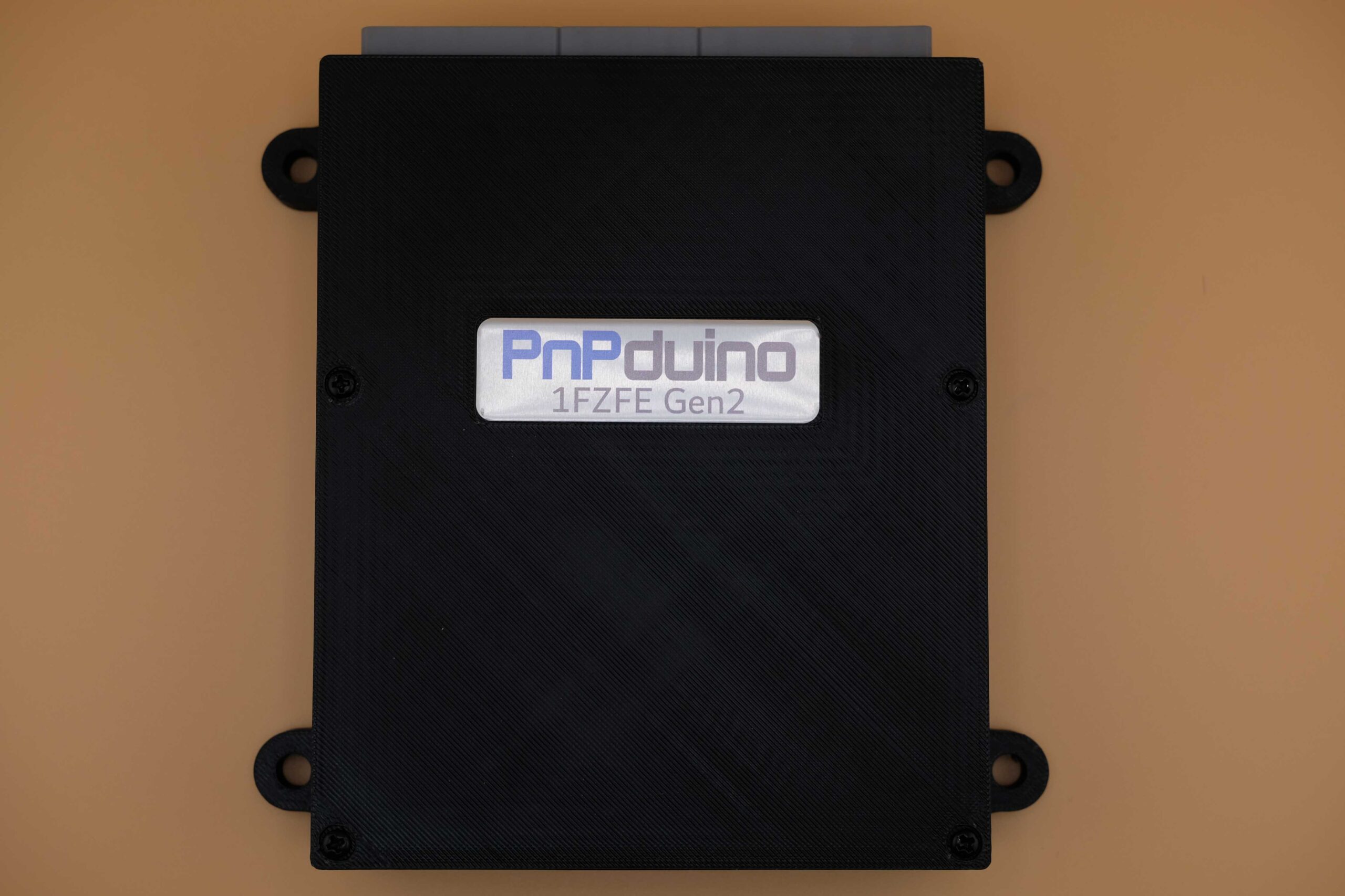
PnPduino Toyota 1FZ-FE Gen2 is a PnPduino programmable engine-management ECU. Manufacturer product information.
Application and identification
Plug-in for the manufacturer's 1998–2002 4.5-litre Toyota Land Cruiser 1FZ-FE Gen2 application, manual transmission only. It uses three vehicle plugs of 26, 16 and 22 positions. The supplier explicitly says Gen2 and Gen3 pinouts differ and must not be interchanged.
System and wiring
A VR conditioner is fitted. The manufacturer describes semi-sequential injection and wasted-spark ignition, stock MAP sensing, and high- or low-impedance injector support. An aftermarket wideband controller is required for proper tuning.
Connector identification
| Connector | Manufacturer description | Scope |
|---|---|---|
| Vehicle connector 1 | 26 positions | See manufacturer for matching Gen2 cavity assignments |
| Vehicle connector 2 | 16 positions | See manufacturer for matching Gen2 cavity assignments |
| Vehicle connector 3 | 22 positions | See manufacturer for matching Gen2 cavity assignments |
The manufacturer’s numbered Gulf-region connector schedules are transcribed below. C3 is shown on the diagram but not identified in its source table, and B2 and B16 share a source row; check the exact loom and manufacturer diagram.
Software and calibration
This listing specifies official Speeduino firmware and use of the SpeedyLoader INI; check the actual build and manufacturer guidance. A supplied base map needs final tuning.
See the PnPduino manufacturer index.
Manufacturer connector assignments
The source labels this diagram for Gulf-country 1FZ-FE Gen2 and views the front of the male ECU connector. Its labels and model-specific hardware differ from the other generation. B2 and B16 share one source row; C3 is pictured but is absent from the source table and is marked accordingly here. Original-vehicle labels, PnPduino assignments and TunerStudio pin numbers are different columns; do not treat an OEM label as evidence of an active ECU connection. Source: PnPduino 1FZ-FE Gen2 pinout. Blank cells reflect the original schedule, not a declaration that the position is spare. The original uses colour to distinguish retained vehicle, unused vehicle and added PnPduino signals; check the original drawing and exact regional loom before wiring.
Connector B
| ECU pin | 1FZ label | 1FZ description | PnPduino connection | PnPduino function | TunerStudio pin | Remarks |
|---|---|---|---|---|---|---|
| B13 | E01 | Power Ground | ||||
| B26 | E02 | Power Ground | ||||
| B12 | INJ1/5 | Injector 1 and 5 | INJ1 | Injector 1 | 8 | |
| B25 | INJ3/6 | Injector 3 and 6 | INJ2 | Injector 2 | 7 | |
| B11 | INJ2/4 | Injector 2 and 4 | INJ3 | Injector 3 | 6 | |
| B24 | INJ4 | Injector 4 | 5 | |||
| B10 | RSD | Rotary ISCV | IDLE1 | Idle 1 | 9 | |
| B23 | IMO | Immobilizer | ||||
| B9 | FAN | Radiator Fan | 24 | Not used by default | ||
| B22 | LC3 | Low Current 3 | 28 | |||
| B8 | TACH | Tachometer Output | TACH | Tachometer Output | 22 | |
| B21 | LC2 | Low Current 2 | 27 | |||
| B7 | ||||||
| B20 | IGT1 | Igniter 1 and 5 | IG1 | Ignition 1 | 35 | |
| B6 | IG4 | Ignition 4 | 34 | Not used by default | ||
| B19 | IGT2 | Igniter 3 and 6 | IG2 | Ignition 2 | 36 | |
| B5 | G2 | CAM signal | VR2+ | VR2+ | 18 | from CAM Sensor |
| B18 | IGT3 | Igniter 2 and 4 | IG3 | Ignition 3 | 33 | |
| B4 | NE+ | CRANK signal | VR1+ | VR1+ | 19 | from CRANK Sensor |
| B17 | NE- | CAM/CRANK Ground | VR1- | VR1- | ||
| B3 | IGF | Ignition Confirmation | ||||
| B2 & B16 | 12VF | Fused 12V | Only for 12V Sensors | |||
| B15 | GRND | Sensor Ground | Only for 12V Sensors | |||
| B1 | IDLE2 | Idle 2 | 10 | Can be used for High Output | ||
| B14 | E1 | Engine Ground |
Connector A
| ECU pin | 1FZ label | 1FZ description | PnPduino connection | PnPduino function | TunerStudio pin | Remarks |
|---|---|---|---|---|---|---|
| A8 | TC | Data Link | ||||
| A16 | VVT | VVT | 11 | Can be used for High Output | ||
| A7 | VAF | Variable Resistor | ||||
| A15 | FPR | Fuel Pump Resistor | ||||
| A6 | CANL | CAN Lo | If STM32 is used | |||
| A14 | CANH | CAN Hi | If STM32 is used | |||
| A5 | KNKL | Knock Sensor Left | KNOCK | Knock | 21 | Not used by default, for future use |
| A13 | KNKR | Knock Sensor Right | FLEX | Flex sensor | 2 | Not used by default |
| A4 | THW | Coolant Temperature | CLT | Engine Coolant Temp | A4 | |
| A12 | IMI | Immobilizer | ||||
| A3 | THA | Intake Air Temperature | IAT | Intake Air Temp | A5 | |
| A11 | VTA | Throttle Position Sensor | TPS | Throttle Position Sensor | A3 | |
| A2 | PIM | MAP sensor | MAP | MAP sensor | A0 | |
| A10 | SIL | Data Link | ||||
| A1 | VC | 5V Sensor Supply | 5V | 5V from ECU | Fused 5V to sensors | |
| A9 | E2 | Sensor Ground |
Connector C
| ECU pin | 1FZ label | 1FZ description | PnPduino connection | PnPduino function | TunerStudio pin | Remarks |
|---|---|---|---|---|---|---|
| C11 | STA | Starter Switch | ||||
| C22 | NSW | Neutral Switch | CLUTCH | Clutch switch | 37 | |
| C10 | A/C1 | AC Amplifier | INP2 | Input 2 | A9 | AC Switch to Idle Up |
| C21 | ACT | AC Control | ||||
| C9 | SPD | Vehicle Speed | VSS | Vehicle Speed | 20 | |
| C20 | INP3 | Input 3 | A10 | |||
| C8 | FPM1 | Main Fuel Pump | ||||
| C19 | FPM2 | Sub Fuel Pump | ||||
| C7 | FPMS | Fuel Tank Change Switch | INP6 | Input 6 | A12 | |
| C18 | INP5 | Input 5 | A6 | |||
| C6 | INP1 | Input 1 | A8 | |||
| C17 | INP4 | Input 4 | A11 | |||
| C5 | W | Check Engine Light | FAN2 | Fan 2 | 25 | Not used by default, for future use |
| C16 | FPR | Fuel Pump Resistor | INP7 | Input 7 | A13 | |
| C4 | FC | Circuit Opening Relay | FP | Fuel Pump | 23 | |
| C15 | FPR2 | Sub Fuel Pump Relay | LC1 | Low Current 1 | 26 | |
| C14 | FPLD | Sub Fuel Indicator Lamp | LC4 | Low Current 4 | 29 | |
| C3 | Position C3 is not listed in the manufacturer table | |||||
| C2 | STP | Stop Light | ||||
| C13 | BOOST | Boost | 12 | Can be used for High Output | ||
| C1 | BATT | Battery Constant 12V | Not used by default | |||
| C12 | +B | Ignition +12V switched | Should be fused 12V supply to ECU |