Removed text is struck through; added text is highlighted.
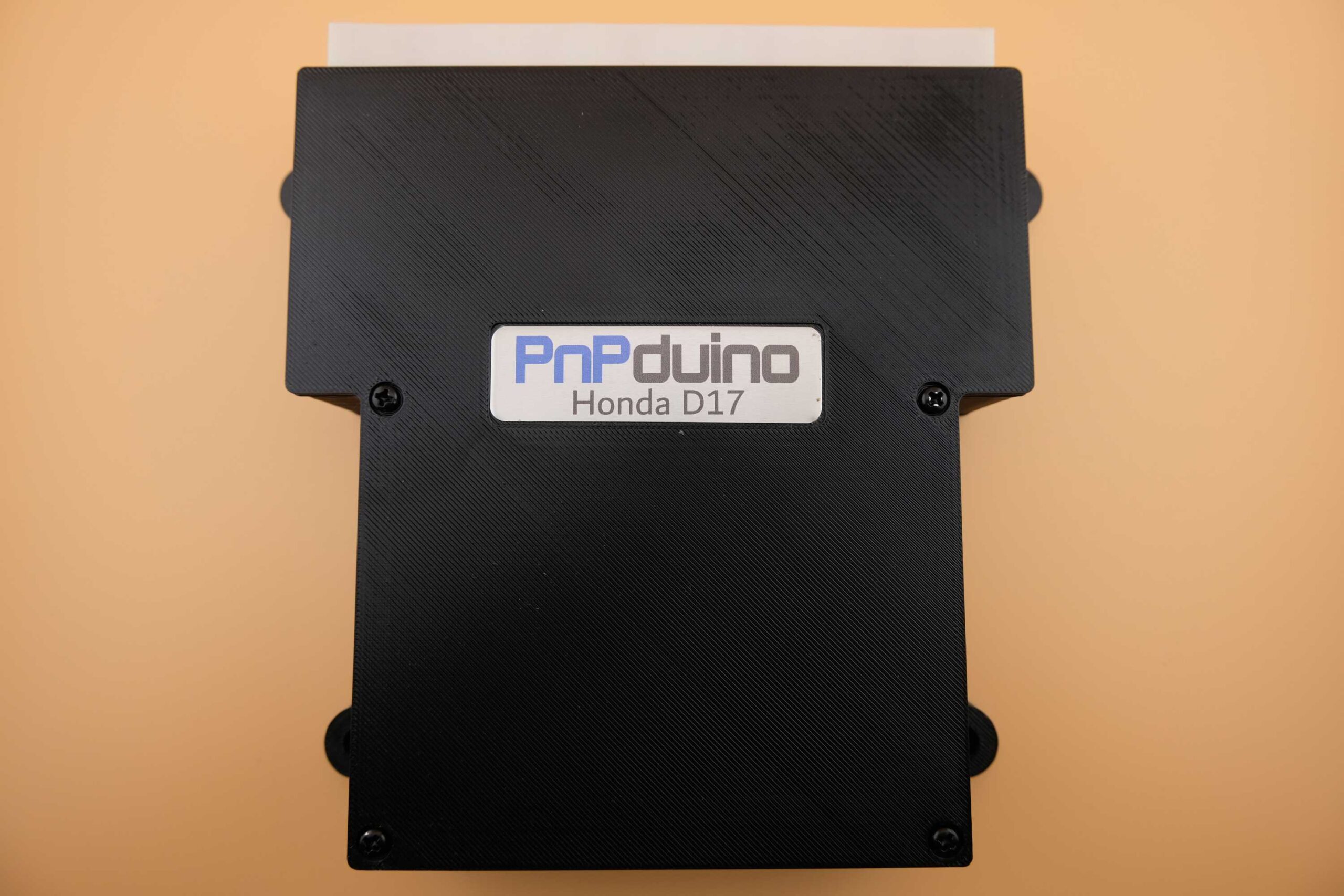
PnPduino Honda Civic D17 is a PnPduino programmable engine-management ECU. Manufacturer product information.
PnPduino Honda Civic D17. PnPduino manufacturer product photograph, reproduced with permission.
Application and identification
Standalone for the 2001–2005 seventh-generation Civic D17A with manual transmission. The manufacturer describes automatic operation only as a piggyback arrangement; it is not a stand-alone automatic-transmission controller.
System and wiring
The product notes say the AC switch must be wired to enable AC control and operation may be affected by parking/headlights. The charge lamp and coolant gauge do not work because of the original multiplex signals. Factory OBD2, CAN and K-line functions are unavailable; OEM wideband and narrowband oxygen sensors are unsupported. Alternator, VTEC and triggers are listed as working.
A complete pin-by-pin ECU connector table has not been verified from the cited product information. Obtain the diagram for the exact model and revision from PnPduino documentation; the vehicle ECU pinout and other PnPduino models must not be assumed interchangeable.
Software and calibration
Uses TunerStudio and the manufacturer’s custom firmware; the supplier says not to update it. An aftermarket wideband controller and final tune are required.
See the PnPduino manufacturer index.
Manufacturer connector assignmentsThe following schedule reproduces the shared K-Series/D17 manufacturer pinout, viewed from the front of the male ECU header. Pairs such as A2/A3 appear on one manufacturer row. B1 is marked unavailable on D17; read all model-specific remarks and the source colour legend. The source groups functions by firing order and notes that PnPduino channel numbers do not necessarily match cylinder numbers. Source: PnPduino Honda K-Series / D17 pinout. Blank cells reflect the original schedule, not a declaration that the position is spare. The original uses colour to distinguish retained vehicle, unused vehicle and added PnPduino signals; check the original drawing and exact regional loom before wiring.Connector AHonda labelECU pinHonda functionPnPduino connectionPnPduino functionTunerStudio pinRemarksPHO2S HTCA1AFR Sensor Heater Ctrl -Not UsedIGP1/IGP2A2/A3Power Source12VBATT12V BatteryPG1/PG2A4/A5Power GroundGRNDECU GroundPower Ground at the Head cover, not Chassis groundPHO2S+A6Oxygen Sensor +O2Oxygen SensorA1Wideband O2 Sensor Linear OutputCKPA7Crankshaft SensorHALL1Hall Sensor 11912+1 Crankshaft sensor signalIMRCA8IMRC Valve Position SensorINP2Input 2A9Intake Manifold Runner Valve Position Sensor or Spare Input 2KSA9Knock SensorHALL4Hall Sensor 421Spare Hall Sensor or Spare InputSGA10/A 11Sensor GroundGRNDECU GroundSensor GroundIACVA12Idle Air Control ValveIDLE1Idle 19Idle 1-A13-CLUTCHClutch37Clutch Switch Input-A14-INP3Input 3A10Spare Input 3TPSA15Throttle Pos sensrTPSThrottle Pos sensrA3Throttle Position SensorPHO2S-A16Oxygen Sensor -GRNDECU GroundECU Ground-A17-INP4Input 4A11Spare Input 4VSSA18Vehicle SpeedVSSVehicle Speed20Vehicle Speed Sensor Input Low Frequency onlyMAPA19Manifold Abs PresMAPManifold Abs PresA0MAP SensorVCCA20 /A21Sensor Voltage5V5V Supply5V Supply to SensorsPHO2S HTC+A22AFR Sensor Heater Ctrl +Not UsedLGA23 /A24Logic GroundGRNDECU GroundLogic GroundCMPA25Camshaft Position SensorHALL3Hall Sensor 33Intake Cam Sensor 4 pulsesTDCA26Top Dead Center SensorHALL2Hall Sensor 218Exhaust Cam Sensor 4+1 pulsesIGPLS4A27Ignition Coil Pulse 4IG3Ignition 333In Firing order 1-3-4-2 (IG3 of PnPduino is actual IG4)IGPLS3A28Ignition Coil Pulse 3IG2Ignition 236In Firing order 1-3-4-2 (IG2 of PnPduino is actual IG3)IGPLS2A29Ignition Coil Pulse 2IG4Ignition 434In Firing order 1-3-4-2 (IG4 of PnPduino is actual IG2)IGPLS1A30Ignition Coil Pulse 1IG1Ignition 135In Firing order 1-3-4-2-A31-INP1Input 1A8Spare Input 1Connector BHonda labelECU pinHonda functionPnPduino connectionPnPduino functionTunerStudio pinRemarksVTC+B1VTC Oil Control +12VBATT12V Battery (Not available for D17)INJ4B2Injector 4INJ3Injector 36In Firing order 1-3-4-2 (INJ3 of PnPduino is actual INJ4)INJ3B3Injector 3INJ2Injector 27In Firing order 1-3-4-2 (INJ2 of PnPduino is actual INJ3)INJ2B4Injector 2INJ4Injector 45In Firing order 1-3-4-2 (INJ4 of PnPduino is actual INJ2)INJ1B5Injector 1INJ1Injector 18In Firing order 1-3-4-2FANCB6Fan ControlFANFan 124Thermo FanRVSB7Reverse LockoutLC2Low Current 227Low Current Output 2ECTB8Engine Coolant TempCLTEngine Coolant TempA4Engine Coolant TempVTPSWB9VTEC Pressure SwitchNot UsedALTLB10Alternator LampNot Used-B11--B12-INP5Input 5A6Spare Input 5ALTFB13Alternator FieldNot UsedLSA+B14A/TNot UsedVTSB15VTEC SolenoidVVTVVT11VTEC +12V outputLSB+B16A/TCANLCAN LoFor STM32 ProcessorIATB17Intake Air TempIATIntake Air TempA5Intake Air TempALTCB18Alternator ControlLC4Low Current 429Low Current Output 4-B19-FLEXFlex Fuel Sensor2Flex Fuel Sensor-B20-BOOSTBoost Solenoid12Boost Control SolenoidPCSB21EVAP purgeNot UsedIMRCB22IMRC SolenoidLC3Low Current 328Low Current Output 3VTC-B23VTC Oil Control -IDLE2Idle 210VVT that controls IDLE2 pin which connects to VTC-LSC+B24A/TCANHCAN HiFor STM32 ProcessorConnector EHonda labelECU pinHonda functionPnPduino connectionPnPduino functionTunerStudio pinRemarksIMO FPRE1Fuel Pump RelayFPFuel Pump23Fuel PumpSHO2SE2Secondary Oxygen SensorNot UsedLG3E3Logic GroundGRNDECU GroundLogic GroundSG3E4Sensor GroundGRNDECU GroundSensor GroundVCC3E5Sensor Voltage5V5V SupplySupply to SensorsSO2S HTCE6SO2S Heater ControlNot UsedMRLYE7PGMFI Main RelayGRNDECU GroundECU GroundAFSHTCRE8AFS Heater Control RelayNot UsedIG1E9Ignition Switch12VBATT12V Battery-E10-GRNDECU GroundSensor Ground Additional by PnPduino-E11-GRNDECU GroundSensor Ground Additional by PnPduino-E12-GRNDECU GroundSensor Ground Additional by PnPduinoILUE13ILUNot UsedFTPE14Fuel Tank PressureNot UsedELDE15Electric Load DetectorINP7Input 7A13Spare Input 7PSPWE16Power Steering Pressure SwitchINP6Input 6A12Spare Input 6 Default to AC Switch-E17-5V5V SupplySupply to SensorsACCE18AC CompressorLC1Low Current 126Low Current 1 Default to AC Compressor-E19-12VFused 12VFused 12V2WBSE20EVAP bypassNot UsedVSVE21EVAP shut valveNot UsedBKSWE22Brake SwitchNot UsedK-LINEE23SCAN signalNot UsedSEFMJE24MultiplexNot UsedVSSOUTE25VSS OutputNot UsedNEPE26Engine Speed OutputTACHOTachometer 12V22Tachometer 12VIMOCDE27Immobilizer SignalNot Used-E28-12VFused 12VFused 12VSCSE29Service Check SignalNot UsedWENE30Write Enable SignalNot UsedMILE31Malfunction Indicator LampFAN2Fan 225Fan 2 Output programmable as MIL
Rendered revisions
Open each version to inspect formatting, tables and photographs.
Standalone for the 2001–2005 seventh-generation Civic D17A with manual transmission. The manufacturer describes automatic operation only as a piggyback arrangement; it is not a stand-alone automatic-transmission controller.
System and wiring
The product notes say the AC switch must be wired to enable AC control and operation may be affected by parking/headlights. The charge lamp and coolant gauge do not work because of the original multiplex signals. Factory OBD2, CAN and K-line functions are unavailable; OEM wideband and narrowband oxygen sensors are unsupported. Alternator, VTEC and triggers are listed as working.
A complete pin-by-pin ECU connector table has not been verified from the cited product information. Obtain the diagram for the exact model and revision from PnPduino documentation; the vehicle ECU pinout and other PnPduino models must not be assumed interchangeable.
Software and calibration
Uses TunerStudio and the manufacturer’s custom firmware; the supplier says not to update it. An aftermarket wideband controller and final tune are required.
Standalone for the 2001–2005 seventh-generation Civic D17A with manual transmission. The manufacturer describes automatic operation only as a piggyback arrangement; it is not a stand-alone automatic-transmission controller.
System and wiring
The product notes say the AC switch must be wired to enable AC control and operation may be affected by parking/headlights. The charge lamp and coolant gauge do not work because of the original multiplex signals. Factory OBD2, CAN and K-line functions are unavailable; OEM wideband and narrowband oxygen sensors are unsupported. Alternator, VTEC and triggers are listed as working.
A complete pin-by-pin ECU connector table has not been verified from the cited product information. Obtain the diagram for the exact model and revision from PnPduino documentation; the vehicle ECU pinout and other PnPduino models must not be assumed interchangeable.
Software and calibration
Uses TunerStudio and the manufacturer’s custom firmware; the supplier says not to update it. An aftermarket wideband controller and final tune are required.
The following schedule reproduces the shared K-Series/D17 manufacturer pinout, viewed from the front of the male ECU header. Pairs such as A2/A3 appear on one manufacturer row. B1 is marked unavailable on D17; read all model-specific remarks and the source colour legend. The source groups functions by firing order and notes that PnPduino channel numbers do not necessarily match cylinder numbers. Source: PnPduino Honda K-Series / D17 pinout. Blank cells reflect the original schedule, not a declaration that the position is spare. The original uses colour to distinguish retained vehicle, unused vehicle and added PnPduino signals; check the original drawing and exact regional loom before wiring.
Connector A
Honda label
ECU pin
Honda function
PnPduino connection
PnPduino function
TunerStudio pin
Remarks
PHO2S HTC
A1
AFR Sensor Heater Ctrl -
Not Used
IGP1/IGP2
A2/A3
Power Source
12V
BATT
12V Battery
PG1/PG2
A4/A5
Power Ground
GRND
ECU Ground
Power Ground at the Head cover, not Chassis ground
PHO2S+
A6
Oxygen Sensor +
O2
Oxygen Sensor
A1
Wideband O2 Sensor Linear Output
CKP
A7
Crankshaft Sensor
HALL1
Hall Sensor 1
19
12+1 Crankshaft sensor signal
IMRC
A8
IMRC Valve Position Sensor
INP2
Input 2
A9
Intake Manifold Runner Valve Position Sensor or Spare Input 2
KS
A9
Knock Sensor
HALL4
Hall Sensor 4
21
Spare Hall Sensor or Spare Input
SG
A10/A 11
Sensor Ground
GRND
ECU Ground
Sensor Ground
IACV
A12
Idle Air Control Valve
IDLE1
Idle 1
9
Idle 1
-
A13
-
CLUTCH
Clutch
37
Clutch Switch Input
-
A14
-
INP3
Input 3
A10
Spare Input 3
TPS
A15
Throttle Pos sensr
TPS
Throttle Pos sensr
A3
Throttle Position Sensor
PHO2S-
A16
Oxygen Sensor -
GRND
ECU Ground
ECU Ground
-
A17
-
INP4
Input 4
A11
Spare Input 4
VSS
A18
Vehicle Speed
VSS
Vehicle Speed
20
Vehicle Speed Sensor Input Low Frequency only
MAP
A19
Manifold Abs Pres
MAP
Manifold Abs Pres
A0
MAP Sensor
VCC
A20 /A21
Sensor Voltage
5V
5V Supply
5V Supply to Sensors
PHO2S HTC+
A22
AFR Sensor Heater Ctrl +
Not Used
LG
A23 /A24
Logic Ground
GRND
ECU Ground
Logic Ground
CMP
A25
Camshaft Position Sensor
HALL3
Hall Sensor 3
3
Intake Cam Sensor 4 pulses
TDC
A26
Top Dead Center Sensor
HALL2
Hall Sensor 2
18
Exhaust Cam Sensor 4+1 pulses
IGPLS4
A27
Ignition Coil Pulse 4
IG3
Ignition 3
33
In Firing order 1-3-4-2 (IG3 of PnPduino is actual IG4)
IGPLS3
A28
Ignition Coil Pulse 3
IG2
Ignition 2
36
In Firing order 1-3-4-2 (IG2 of PnPduino is actual IG3)
IGPLS2
A29
Ignition Coil Pulse 2
IG4
Ignition 4
34
In Firing order 1-3-4-2 (IG4 of PnPduino is actual IG2)
IGPLS1
A30
Ignition Coil Pulse 1
IG1
Ignition 1
35
In Firing order 1-3-4-2
-
A31
-
INP1
Input 1
A8
Spare Input 1
Connector B
Honda label
ECU pin
Honda function
PnPduino connection
PnPduino function
TunerStudio pin
Remarks
VTC+
B1
VTC Oil Control +
12V
BATT
12V Battery (Not available for D17)
INJ4
B2
Injector 4
INJ3
Injector 3
6
In Firing order 1-3-4-2 (INJ3 of PnPduino is actual INJ4)
INJ3
B3
Injector 3
INJ2
Injector 2
7
In Firing order 1-3-4-2 (INJ2 of PnPduino is actual INJ3)
INJ2
B4
Injector 2
INJ4
Injector 4
5
In Firing order 1-3-4-2 (INJ4 of PnPduino is actual INJ2)
INJ1
B5
Injector 1
INJ1
Injector 1
8
In Firing order 1-3-4-2
FANC
B6
Fan Control
FAN
Fan 1
24
Thermo Fan
RVS
B7
Reverse Lockout
LC2
Low Current 2
27
Low Current Output 2
ECT
B8
Engine Coolant Temp
CLT
Engine Coolant Temp
A4
Engine Coolant Temp
VTPSW
B9
VTEC Pressure Switch
Not Used
ALTL
B10
Alternator Lamp
Not Used
-
B11
-
-
B12
-
INP5
Input 5
A6
Spare Input 5
ALTF
B13
Alternator Field
Not Used
LSA+
B14
A/T
Not Used
VTS
B15
VTEC Solenoid
VVT
VVT
11
VTEC +12V output
LSB+
B16
A/T
CANL
CAN Lo
For STM32 Processor
IAT
B17
Intake Air Temp
IAT
Intake Air Temp
A5
Intake Air Temp
ALTC
B18
Alternator Control
LC4
Low Current 4
29
Low Current Output 4
-
B19
-
FLEX
Flex Fuel Sensor
2
Flex Fuel Sensor
-
B20
-
BOOST
Boost Solenoid
12
Boost Control Solenoid
PCS
B21
EVAP purge
Not Used
IMRC
B22
IMRC Solenoid
LC3
Low Current 3
28
Low Current Output 3
VTC-
B23
VTC Oil Control -
IDLE2
Idle 2
10
VVT that controls IDLE2 pin which connects to VTC-