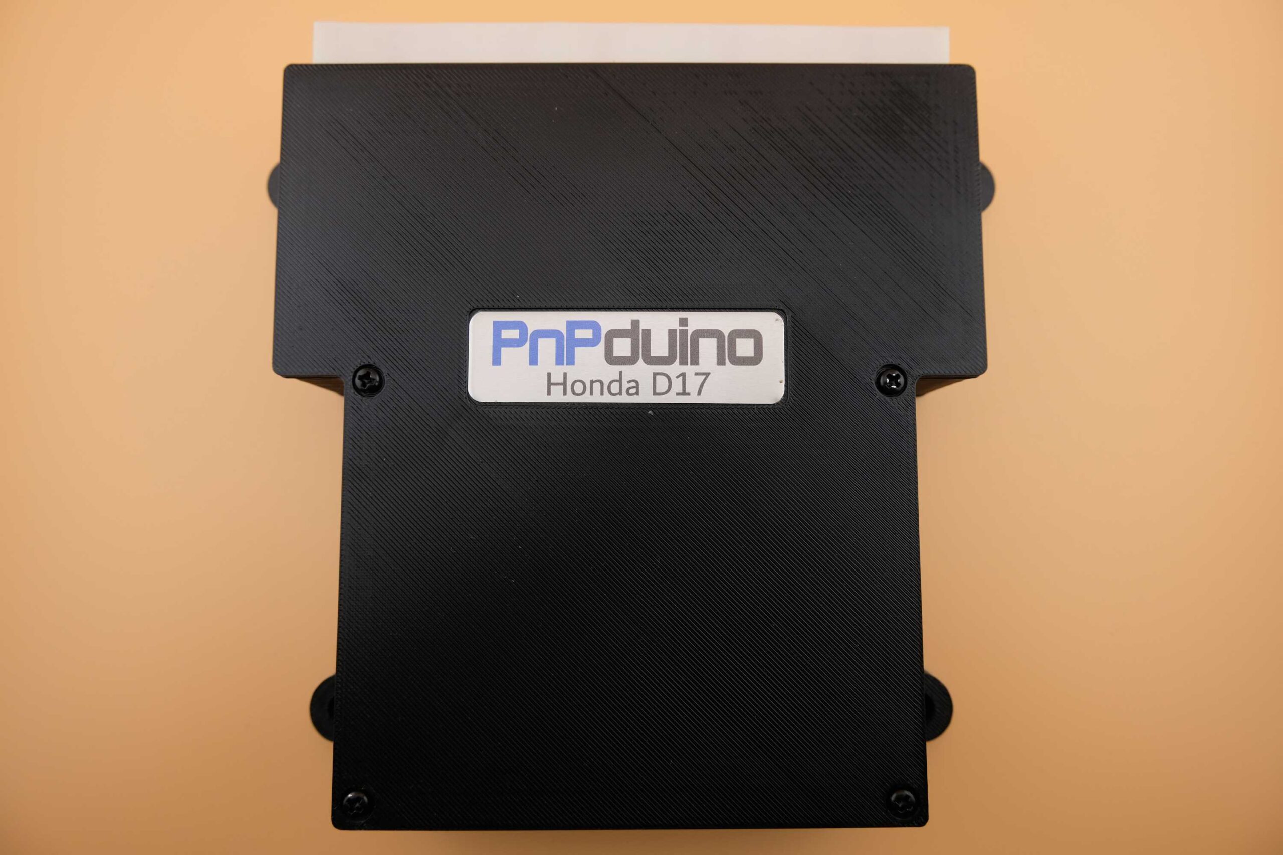
PnPduino Honda Civic D17 is a PnPduino programmable engine-management ECU. Manufacturer product information.
Application and identification
Standalone for the 2001–2005 seventh-generation Civic D17A with manual transmission. The manufacturer describes automatic operation only as a piggyback arrangement; it is not a stand-alone automatic-transmission controller.
System and wiring
The product notes say the AC switch must be wired to enable AC control and operation may be affected by parking/headlights. The charge lamp and coolant gauge do not work because of the original multiplex signals. Factory OBD2, CAN and K-line functions are unavailable; OEM wideband and narrowband oxygen sensors are unsupported. Alternator, VTEC and triggers are listed as working.
A complete pin-by-pin ECU connector table has not been verified from the cited product information. Obtain the diagram for the exact model and revision from PnPduino documentation; the vehicle ECU pinout and other PnPduino models must not be assumed interchangeable.
Software and calibration
Uses TunerStudio and the manufacturer’s custom firmware; the supplier says not to update it. An aftermarket wideband controller and final tune are required.
See the PnPduino manufacturer index.
Manufacturer connector assignments
The following schedule reproduces the shared K-Series/D17 manufacturer pinout, viewed from the front of the male ECU header. Pairs such as A2/A3 appear on one manufacturer row. B1 is marked unavailable on D17; read all model-specific remarks and the source colour legend. The source groups functions by firing order and notes that PnPduino channel numbers do not necessarily match cylinder numbers. Source: PnPduino Honda K-Series / D17 pinout. Blank cells reflect the original schedule, not a declaration that the position is spare. The original uses colour to distinguish retained vehicle, unused vehicle and added PnPduino signals; check the original drawing and exact regional loom before wiring.
Connector A
| Honda label | ECU pin | Honda function | PnPduino connection | PnPduino function | TunerStudio pin | Remarks |
|---|---|---|---|---|---|---|
| PHO2S HTC | A1 | AFR Sensor Heater Ctrl - | Not Used | |||
| IGP1/IGP2 | A2/A3 | Power Source | 12V | BATT | 12V Battery | |
| PG1/PG2 | A4/A5 | Power Ground | GRND | ECU Ground | Power Ground at the Head cover, not Chassis ground | |
| PHO2S+ | A6 | Oxygen Sensor + | O2 | Oxygen Sensor | A1 | Wideband O2 Sensor Linear Output |
| CKP | A7 | Crankshaft Sensor | HALL1 | Hall Sensor 1 | 19 | 12+1 Crankshaft sensor signal |
| IMRC | A8 | IMRC Valve Position Sensor | INP2 | Input 2 | A9 | Intake Manifold Runner Valve Position Sensor or Spare Input 2 |
| KS | A9 | Knock Sensor | HALL4 | Hall Sensor 4 | 21 | Spare Hall Sensor or Spare Input |
| SG | A10/A 11 | Sensor Ground | GRND | ECU Ground | Sensor Ground | |
| IACV | A12 | Idle Air Control Valve | IDLE1 | Idle 1 | 9 | Idle 1 |
| - | A13 | - | CLUTCH | Clutch | 37 | Clutch Switch Input |
| - | A14 | - | INP3 | Input 3 | A10 | Spare Input 3 |
| TPS | A15 | Throttle Pos sensr | TPS | Throttle Pos sensr | A3 | Throttle Position Sensor |
| PHO2S- | A16 | Oxygen Sensor - | GRND | ECU Ground | ECU Ground | |
| - | A17 | - | INP4 | Input 4 | A11 | Spare Input 4 |
| VSS | A18 | Vehicle Speed | VSS | Vehicle Speed | 20 | Vehicle Speed Sensor Input Low Frequency only |
| MAP | A19 | Manifold Abs Pres | MAP | Manifold Abs Pres | A0 | MAP Sensor |
| VCC | A20 /A21 | Sensor Voltage | 5V | 5V Supply | 5V Supply to Sensors | |
| PHO2S HTC+ | A22 | AFR Sensor Heater Ctrl + | Not Used | |||
| LG | A23 /A24 | Logic Ground | GRND | ECU Ground | Logic Ground | |
| CMP | A25 | Camshaft Position Sensor | HALL3 | Hall Sensor 3 | 3 | Intake Cam Sensor 4 pulses |
| TDC | A26 | Top Dead Center Sensor | HALL2 | Hall Sensor 2 | 18 | Exhaust Cam Sensor 4+1 pulses |
| IGPLS4 | A27 | Ignition Coil Pulse 4 | IG3 | Ignition 3 | 33 | In Firing order 1-3-4-2 (IG3 of PnPduino is actual IG4) |
| IGPLS3 | A28 | Ignition Coil Pulse 3 | IG2 | Ignition 2 | 36 | In Firing order 1-3-4-2 (IG2 of PnPduino is actual IG3) |
| IGPLS2 | A29 | Ignition Coil Pulse 2 | IG4 | Ignition 4 | 34 | In Firing order 1-3-4-2 (IG4 of PnPduino is actual IG2) |
| IGPLS1 | A30 | Ignition Coil Pulse 1 | IG1 | Ignition 1 | 35 | In Firing order 1-3-4-2 |
| - | A31 | - | INP1 | Input 1 | A8 | Spare Input 1 |
Connector B
| Honda label | ECU pin | Honda function | PnPduino connection | PnPduino function | TunerStudio pin | Remarks |
|---|---|---|---|---|---|---|
| VTC+ | B1 | VTC Oil Control + | 12V | BATT | 12V Battery (Not available for D17) | |
| INJ4 | B2 | Injector 4 | INJ3 | Injector 3 | 6 | In Firing order 1-3-4-2 (INJ3 of PnPduino is actual INJ4) |
| INJ3 | B3 | Injector 3 | INJ2 | Injector 2 | 7 | In Firing order 1-3-4-2 (INJ2 of PnPduino is actual INJ3) |
| INJ2 | B4 | Injector 2 | INJ4 | Injector 4 | 5 | In Firing order 1-3-4-2 (INJ4 of PnPduino is actual INJ2) |
| INJ1 | B5 | Injector 1 | INJ1 | Injector 1 | 8 | In Firing order 1-3-4-2 |
| FANC | B6 | Fan Control | FAN | Fan 1 | 24 | Thermo Fan |
| RVS | B7 | Reverse Lockout | LC2 | Low Current 2 | 27 | Low Current Output 2 |
| ECT | B8 | Engine Coolant Temp | CLT | Engine Coolant Temp | A4 | Engine Coolant Temp |
| VTPSW | B9 | VTEC Pressure Switch | Not Used | |||
| ALTL | B10 | Alternator Lamp | Not Used | |||
| - | B11 | - | ||||
| - | B12 | - | INP5 | Input 5 | A6 | Spare Input 5 |
| ALTF | B13 | Alternator Field | Not Used | |||
| LSA+ | B14 | A/T | Not Used | |||
| VTS | B15 | VTEC Solenoid | VVT | VVT | 11 | VTEC +12V output |
| LSB+ | B16 | A/T | CANL | CAN Lo | For STM32 Processor | |
| IAT | B17 | Intake Air Temp | IAT | Intake Air Temp | A5 | Intake Air Temp |
| ALTC | B18 | Alternator Control | LC4 | Low Current 4 | 29 | Low Current Output 4 |
| - | B19 | - | FLEX | Flex Fuel Sensor | 2 | Flex Fuel Sensor |
| - | B20 | - | BOOST | Boost Solenoid | 12 | Boost Control Solenoid |
| PCS | B21 | EVAP purge | Not Used | |||
| IMRC | B22 | IMRC Solenoid | LC3 | Low Current 3 | 28 | Low Current Output 3 |
| VTC- | B23 | VTC Oil Control - | IDLE2 | Idle 2 | 10 | VVT that controls IDLE2 pin which connects to VTC- |
| LSC+ | B24 | A/T | CANH | CAN Hi | For STM32 Processor |
Connector E
| Honda label | ECU pin | Honda function | PnPduino connection | PnPduino function | TunerStudio pin | Remarks |
|---|---|---|---|---|---|---|
| IMO FPR | E1 | Fuel Pump Relay | FP | Fuel Pump | 23 | Fuel Pump |
| SHO2S | E2 | Secondary Oxygen Sensor | Not Used | |||
| LG3 | E3 | Logic Ground | GRND | ECU Ground | Logic Ground | |
| SG3 | E4 | Sensor Ground | GRND | ECU Ground | Sensor Ground | |
| VCC3 | E5 | Sensor Voltage | 5V | 5V Supply | Supply to Sensors | |
| SO2S HTC | E6 | SO2S Heater Control | Not Used | |||
| MRLY | E7 | PGMFI Main Relay | GRND | ECU Ground | ECU Ground | |
| AFSHTCR | E8 | AFS Heater Control Relay | Not Used | |||
| IG1 | E9 | Ignition Switch | 12V | BATT | 12V Battery | |
| - | E10 | - | GRND | ECU Ground | Sensor Ground Additional by PnPduino | |
| - | E11 | - | GRND | ECU Ground | Sensor Ground Additional by PnPduino | |
| - | E12 | - | GRND | ECU Ground | Sensor Ground Additional by PnPduino | |
| ILU | E13 | ILU | Not Used | |||
| FTP | E14 | Fuel Tank Pressure | Not Used | |||
| ELD | E15 | Electric Load Detector | INP7 | Input 7 | A13 | Spare Input 7 |
| PSPW | E16 | Power Steering Pressure Switch | INP6 | Input 6 | A12 | Spare Input 6 Default to AC Switch |
| - | E17 | - | 5V | 5V Supply | Supply to Sensors | |
| ACC | E18 | AC Compressor | LC1 | Low Current 1 | 26 | Low Current 1 Default to AC Compressor |
| - | E19 | - | 12V | Fused 12V | Fused 12V | |
| 2WBS | E20 | EVAP bypass | Not Used | |||
| VSV | E21 | EVAP shut valve | Not Used | |||
| BKSW | E22 | Brake Switch | Not Used | |||
| K-LINE | E23 | SCAN signal | Not Used | |||
| SEFMJ | E24 | Multiplex | Not Used | |||
| VSSOUT | E25 | VSS Output | Not Used | |||
| NEP | E26 | Engine Speed Output | TACHO | Tachometer 12V | 22 | Tachometer 12V |
| IMOCD | E27 | Immobilizer Signal | Not Used | |||
| - | E28 | - | 12V | Fused 12V | Fused 12V | |
| SCS | E29 | Service Check Signal | Not Used | |||
| WEN | E30 | Write Enable Signal | Not Used | |||
| MIL | E31 | Malfunction Indicator Lamp | FAN2 | Fan 2 | 25 | Fan 2 Output programmable as MIL |