by llandowtuninguk@gmail.com Expand SportDevices controller generations, inputs, brake power supplies and retrofit details using manufacturer documentation.
Removed text is struck through; added text is highlighted.
SportDevices designs dynamometers and instrumentation for engine and vehicle testing. Its SP-series units measure signals and, depending on model and installed hardware, control a brake. A controller kit and a complete dynamometer are different purchases; a frame, roller, absorber and supporting equipment may be supplied separately. See Dynamometers and the manufacturers directory.
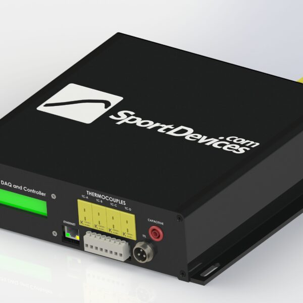
SP5 dyno data-acquisition and control unit. Image: SportDevices SP5 product page, used with permission.
History and scope
SportDevices states that José Andani and José Luis Cortés founded the business in 2001. Its own history identifies the SP1 as an established early controller and describes products for motorcycle chassis, engine and shock-absorber test systems. The company lists its headquarters near Valencia, Spain. SportDevices: about.
Dyno and test applications
Its documentation covers motorcycle and car rolling roads, engine test beds and hub dynos. These are installation types, not evidence that a single controller or frame automatically supports all of them. The SP5 product guide illustrates single-axle roller layouts, AWD and two-brake hub use with the appropriate sensors, power supplies and configuration.
Controllers and software
SP1 and SP1+: the manufacturer lists the SP1 as a single-roller-channel unit; the SP1+ adds a load-cell input and brake output in its comparison. Check the exact model and installed options.SP5: a brake-dyno data-acquisition and control unit with two roller or brake speed channels and load-cell inputs. SportDevices describes inertial, steady, ramp and fixed-brake modes. Its AWD arrangement needs additional components and activation.SP6: the manufacturer's comparison lists configurations with up to four roller channels and a four-brake hub option. Installation and features depend on variant.
SportDyno software provides acquisition, graphs, test comparison and selectable test modes; functionality and licensing vary. An eddy-current brake requires a compatible power supply and control circuit, and a water brake needs its own valve actuator. Controller commands alone do not add braking or motoring capability to a dyno.
Identifying an installation
Record the frame and absorber maker as well as the SP unit, firmware and SportDyno version, channel count, speed pickups, load cells and power module. A retrofitted controller does not change the mechanical ratings of the original dyno. See dynamometer control systems and the manufacturer manuals.
SP controller generations in detail
SportDevices sells both complete dyno products and instrumentation for existing machines. The electronics, software licence, brake power supply and sensors must be matched to the particular absorber and installation. The following table combines the manufacturer's product information with its older SP3 and SP4 documentation; older models are historical examples and current availability is not assumed. SP5 and family comparison; SP6 product information.
ModelMeasurement and controlTypical application and limits
SP1 V4Single roller-speed input, engine RPM, four 0–5 V analogue inputs and two K-type thermocouple inputs; basic inertia acquisition.An inertia-dyno kit; the standard SP1 in the manufacturer's comparison has no load-cell channel or brake output. Do not confuse it with SP1+. SP1 V4.
SP1+ V5One roller RPM, one engine RPM, one load cell, four analogue and two K-type inputs; one PWM brake command and one servo output.Single-brake version; the listed kit includes a PWS3.3 brake power supply, while DAQ-only and other configurations differ. SP1+ V5.
SP3Historical acquisition kit: roller RPM, engine RPM, K-type temperature, one general analogue input and one load-cell input.For instrumenting an existing brake dyno, including water and eddy brakes. The historical supplier page explicitly states SP3 does not control the brake; existing brake control is required. SP3 description.
SP4Historical digital PID speed controller with one roller/brake-speed input, engine RPM, one load cell, PWM brake command, analogue and K-type inputs, relay and servo outputs.Its documentation describes constant-speed and ramp modes and stand-alone or computer-connected operation. SP4 description.
SP5Two roller/brake-speed channels, two load-cell channels, six 0–5 V analogue inputs, eight K-type inputs, two brake outputs and one CAN bus in the manufacturer's comparison.Single-axle, AWD or two-brake/two-hub arrangements as configured. AWD synchronisation needs the appropriate firmware, second speed sensor, load cell and power supply; a DAQ-only unit is not the complete kit. SP5 product information.
SP6 2WD / AWD / HUB-4Four roller/brake-speed inputs, eight 0–5 V analogue inputs, eight K-type inputs, four brake outputs and two CAN buses. The comparison lists two load-cell channels in 2WD/AWD and four in HUB-4.Described for two-hub and four-hub systems and AWD twin-roller layouts; the exact channel configuration, sensors, separate power supplies and activation must match the chosen kit. SP6 product information.
The manufacturer presents the SP5 and SP6 as closed-loop brake controllers with inertial, steady, ramp and fixed-brake modes, and says they can operate without a PC using a compatible remote; check whether the remote is included in the chosen package. The SportDyno feature page also lists step and programmed tests. Road simulation is listed as licensed; other product-page text describes it as future software, so verify the exact firmware, software version and licence instead of assuming that it is included.The manufacturer presents the SP5 and SP6 as closed-loop brake controllers with inertial, steady, ramp and fixed-brake modes, and says the supplied remote can operate them without a PC. The SportDyno feature page also lists step and programmed tests. Road simulation is listed as licensed; other product-page text describes it as future software, so verify the exact firmware, software version and licence instead of assuming that it is included.
Hardware interfaces and brake actuation
In a brake-equipped system, a speed pickup measures roller, brake or hub speed and a load cell measures absorber reaction through a calibrated arm. Engine RPM can use an appropriate pickup; analogue and thermocouple inputs add channels such as temperatures or external sensor signals. The controller compares target and measured speed and sends a low-power command to a separate brake driver. SP5 and SP6 list PWM brake commands, relay outputs and a throttle/servo output. Their published interfaces include Ethernet and CAN; SP6 lists two CAN buses compared with SP5's one. Actual interfaces and enabled functions depend on the device generation and configuration. SP5; SP6.
For an eddy-current brake, the separate driver must be compatible with the brake coil and supply. SportDevices lists the PWS3.3 power supply and publishes a PWS3.x / HS-PWS manual describing different power-stage designs. The manual's inductive discharge and response features concern the brake excitation circuit and do not by themselves establish vehicle-power regeneration. Brake voltage, current, wiring, cooling, interlocks and power-stage compatibility must be checked for the individual installation.
Software, setup and retrofit checks
SportDyno provides real-time acquisition, comparison graphs, guided tests, filters and configured test modes. The maker's downloads page lists controller and power-supply manuals, a software manual, load-cell calibration, roller-inertia adjustment and PID-tuning guides. Graphs and correction settings need to be interpreted alongside the test method and hardware configuration; software cannot increase the mechanical or thermal rating of a dyno.
A retrofit should identify the existing dyno frame and brake, speed sensor and tooth count, load-cell type and reaction-arm geometry, power supply and available control interface. Establish the number of independently measured and driven brakes, licence and firmware requirements, and whether the existing safety, emergency-stop and cooling arrangements remain compatible. Do not assume that connectors or outputs are interchangeable across generations.
The quick dyno guide explains the maker's calibration-arm and known-weight method and distinguishes the zeroing procedure for SP1+/SP5/SP6 from SP3/SP4. Follow the manual for the actual revision and installation, check the resulting calibration, and validate control response before testing a vehicle.
Details are based on the linked manufacturer sources checked 17 November 2026; configurations and availability can change.
Related comparison: Compare factory and aftermarket dynamometer controllers.
Rendered revisions
Open each version to inspect formatting, tables and photographs.
Revision 2: SportDevices dynamometers and controllers
SportDevices designs dynamometers and instrumentation for engine and vehicle testing. Its SP-series units measure signals and, depending on model and installed hardware, control a brake. A controller kit and a complete dynamometer are different purchases; a frame, roller, absorber and supporting equipment may be supplied separately. See Dynamometers and the manufacturers directory.
SportDevices states that José Andani and José Luis Cortés founded the business in 2001. Its own history identifies the SP1 as an established early controller and describes products for motorcycle chassis, engine and shock-absorber test systems. The company lists its headquarters near Valencia, Spain. SportDevices: about.
Dyno and test applications
Its documentation covers motorcycle and car rolling roads, engine test beds and hub dynos. These are installation types, not evidence that a single controller or frame automatically supports all of them. The SP5 product guide illustrates single-axle roller layouts, AWD and two-brake hub use with the appropriate sensors, power supplies and configuration.
Controllers and software
SP1 and SP1+: the manufacturer lists the SP1 as a single-roller-channel unit; the SP1+ adds a load-cell input and brake output in its comparison. Check the exact model and installed options.
SP5: a brake-dyno data-acquisition and control unit with two roller or brake speed channels and load-cell inputs. SportDevices describes inertial, steady, ramp and fixed-brake modes. Its AWD arrangement needs additional components and activation.
SP6: the manufacturer's comparison lists configurations with up to four roller channels and a four-brake hub option. Installation and features depend on variant.
SportDyno software provides acquisition, graphs, test comparison and selectable test modes; functionality and licensing vary. An eddy-current brake requires a compatible power supply and control circuit, and a water brake needs its own valve actuator. Controller commands alone do not add braking or motoring capability to a dyno.
Identifying an installation
Record the frame and absorber maker as well as the SP unit, firmware and SportDyno version, channel count, speed pickups, load cells and power module. A retrofitted controller does not change the mechanical ratings of the original dyno. See dynamometer control systems and the manufacturer manuals.
SP controller generations in detail
SportDevices sells both complete dyno products and instrumentation for existing machines. The electronics, software licence, brake power supply and sensors must be matched to the particular absorber and installation. The following table combines the manufacturer's product information with its older SP3 and SP4 documentation; older models are historical examples and current availability is not assumed. SP5 and family comparison; SP6 product information.
Model
Measurement and control
Typical application and limits
SP1 V4
Single roller-speed input, engine RPM, four 0–5 V analogue inputs and two K-type thermocouple inputs; basic inertia acquisition.
An inertia-dyno kit; the standard SP1 in the manufacturer's comparison has no load-cell channel or brake output. Do not confuse it with SP1+. SP1 V4.
SP1+ V5
One roller RPM, one engine RPM, one load cell, four analogue and two K-type inputs; one PWM brake command and one servo output.
Single-brake version; the listed kit includes a PWS3.3 brake power supply, while DAQ-only and other configurations differ. SP1+ V5.
SP3
Historical acquisition kit: roller RPM, engine RPM, K-type temperature, one general analogue input and one load-cell input.
For instrumenting an existing brake dyno, including water and eddy brakes. The historical supplier page explicitly states SP3 does not control the brake; existing brake control is required. SP3 description.
SP4
Historical digital PID speed controller with one roller/brake-speed input, engine RPM, one load cell, PWM brake command, analogue and K-type inputs, relay and servo outputs.
Its documentation describes constant-speed and ramp modes and stand-alone or computer-connected operation. SP4 description.
SP5
Two roller/brake-speed channels, two load-cell channels, six 0–5 V analogue inputs, eight K-type inputs, two brake outputs and one CAN bus in the manufacturer's comparison.
Single-axle, AWD or two-brake/two-hub arrangements as configured. AWD synchronisation needs the appropriate firmware, second speed sensor, load cell and power supply; a DAQ-only unit is not the complete kit. SP5 product information.
SP6 2WD / AWD / HUB-4
Four roller/brake-speed inputs, eight 0–5 V analogue inputs, eight K-type inputs, four brake outputs and two CAN buses. The comparison lists two load-cell channels in 2WD/AWD and four in HUB-4.
Described for two-hub and four-hub systems and AWD twin-roller layouts; the exact channel configuration, sensors, separate power supplies and activation must match the chosen kit. SP6 product information.
The manufacturer presents the SP5 and SP6 as closed-loop brake controllers with inertial, steady, ramp and fixed-brake modes, and says the supplied remote can operate them without a PC. The SportDyno feature page also lists step and programmed tests. Road simulation is listed as licensed; other product-page text describes it as future software, so verify the exact firmware, software version and licence instead of assuming that it is included.
Hardware interfaces and brake actuation
In a brake-equipped system, a speed pickup measures roller, brake or hub speed and a load cell measures absorber reaction through a calibrated arm. Engine RPM can use an appropriate pickup; analogue and thermocouple inputs add channels such as temperatures or external sensor signals. The controller compares target and measured speed and sends a low-power command to a separate brake driver. SP5 and SP6 list PWM brake commands, relay outputs and a throttle/servo output. Their published interfaces include Ethernet and CAN; SP6 lists two CAN buses compared with SP5's one. Actual interfaces and enabled functions depend on the device generation and configuration. SP5; SP6.
For an eddy-current brake, the separate driver must be compatible with the brake coil and supply. SportDevices lists the PWS3.3 power supply and publishes a PWS3.x / HS-PWS manual describing different power-stage designs. The manual's inductive discharge and response features concern the brake excitation circuit and do not by themselves establish vehicle-power regeneration. Brake voltage, current, wiring, cooling, interlocks and power-stage compatibility must be checked for the individual installation.
Software, setup and retrofit checks
SportDyno provides real-time acquisition, comparison graphs, guided tests, filters and configured test modes. The maker's downloads page lists controller and power-supply manuals, a software manual, load-cell calibration, roller-inertia adjustment and PID-tuning guides. Graphs and correction settings need to be interpreted alongside the test method and hardware configuration; software cannot increase the mechanical or thermal rating of a dyno.
A retrofit should identify the existing dyno frame and brake, speed sensor and tooth count, load-cell type and reaction-arm geometry, power supply and available control interface. Establish the number of independently measured and driven brakes, licence and firmware requirements, and whether the existing safety, emergency-stop and cooling arrangements remain compatible. Do not assume that connectors or outputs are interchangeable across generations.
The quick dyno guide explains the maker's calibration-arm and known-weight method and distinguishes the zeroing procedure for SP1+/SP5/SP6 from SP3/SP4. Follow the manual for the actual revision and installation, check the resulting calibration, and validate control response before testing a vehicle.
Details are based on the linked manufacturer sources checked 17 November 2026; configurations and availability can change.
Revision 4: SportDevices dynamometers and controllers
SportDevices designs dynamometers and instrumentation for engine and vehicle testing. Its SP-series units measure signals and, depending on model and installed hardware, control a brake. A controller kit and a complete dynamometer are different purchases; a frame, roller, absorber and supporting equipment may be supplied separately. See Dynamometers and the manufacturers directory.
SportDevices states that José Andani and José Luis Cortés founded the business in 2001. Its own history identifies the SP1 as an established early controller and describes products for motorcycle chassis, engine and shock-absorber test systems. The company lists its headquarters near Valencia, Spain. SportDevices: about.
Dyno and test applications
Its documentation covers motorcycle and car rolling roads, engine test beds and hub dynos. These are installation types, not evidence that a single controller or frame automatically supports all of them. The SP5 product guide illustrates single-axle roller layouts, AWD and two-brake hub use with the appropriate sensors, power supplies and configuration.
Controllers and software
SP1 and SP1+: the manufacturer lists the SP1 as a single-roller-channel unit; the SP1+ adds a load-cell input and brake output in its comparison. Check the exact model and installed options.
SP5: a brake-dyno data-acquisition and control unit with two roller or brake speed channels and load-cell inputs. SportDevices describes inertial, steady, ramp and fixed-brake modes. Its AWD arrangement needs additional components and activation.
SP6: the manufacturer's comparison lists configurations with up to four roller channels and a four-brake hub option. Installation and features depend on variant.
SportDyno software provides acquisition, graphs, test comparison and selectable test modes; functionality and licensing vary. An eddy-current brake requires a compatible power supply and control circuit, and a water brake needs its own valve actuator. Controller commands alone do not add braking or motoring capability to a dyno.
Identifying an installation
Record the frame and absorber maker as well as the SP unit, firmware and SportDyno version, channel count, speed pickups, load cells and power module. A retrofitted controller does not change the mechanical ratings of the original dyno. See dynamometer control systems and the manufacturer manuals.
SP controller generations in detail
SportDevices sells both complete dyno products and instrumentation for existing machines. The electronics, software licence, brake power supply and sensors must be matched to the particular absorber and installation. The following table combines the manufacturer's product information with its older SP3 and SP4 documentation; older models are historical examples and current availability is not assumed. SP5 and family comparison; SP6 product information.
Model
Measurement and control
Typical application and limits
SP1 V4
Single roller-speed input, engine RPM, four 0–5 V analogue inputs and two K-type thermocouple inputs; basic inertia acquisition.
An inertia-dyno kit; the standard SP1 in the manufacturer's comparison has no load-cell channel or brake output. Do not confuse it with SP1+. SP1 V4.
SP1+ V5
One roller RPM, one engine RPM, one load cell, four analogue and two K-type inputs; one PWM brake command and one servo output.
Single-brake version; the listed kit includes a PWS3.3 brake power supply, while DAQ-only and other configurations differ. SP1+ V5.
SP3
Historical acquisition kit: roller RPM, engine RPM, K-type temperature, one general analogue input and one load-cell input.
For instrumenting an existing brake dyno, including water and eddy brakes. The historical supplier page explicitly states SP3 does not control the brake; existing brake control is required. SP3 description.
SP4
Historical digital PID speed controller with one roller/brake-speed input, engine RPM, one load cell, PWM brake command, analogue and K-type inputs, relay and servo outputs.
Its documentation describes constant-speed and ramp modes and stand-alone or computer-connected operation. SP4 description.
SP5
Two roller/brake-speed channels, two load-cell channels, six 0–5 V analogue inputs, eight K-type inputs, two brake outputs and one CAN bus in the manufacturer's comparison.
Single-axle, AWD or two-brake/two-hub arrangements as configured. AWD synchronisation needs the appropriate firmware, second speed sensor, load cell and power supply; a DAQ-only unit is not the complete kit. SP5 product information.
SP6 2WD / AWD / HUB-4
Four roller/brake-speed inputs, eight 0–5 V analogue inputs, eight K-type inputs, four brake outputs and two CAN buses. The comparison lists two load-cell channels in 2WD/AWD and four in HUB-4.
Described for two-hub and four-hub systems and AWD twin-roller layouts; the exact channel configuration, sensors, separate power supplies and activation must match the chosen kit. SP6 product information.
The manufacturer presents the SP5 and SP6 as closed-loop brake controllers with inertial, steady, ramp and fixed-brake modes, and says they can operate without a PC using a compatible remote; check whether the remote is included in the chosen package. The SportDyno feature page also lists step and programmed tests. Road simulation is listed as licensed; other product-page text describes it as future software, so verify the exact firmware, software version and licence instead of assuming that it is included.
Hardware interfaces and brake actuation
In a brake-equipped system, a speed pickup measures roller, brake or hub speed and a load cell measures absorber reaction through a calibrated arm. Engine RPM can use an appropriate pickup; analogue and thermocouple inputs add channels such as temperatures or external sensor signals. The controller compares target and measured speed and sends a low-power command to a separate brake driver. SP5 and SP6 list PWM brake commands, relay outputs and a throttle/servo output. Their published interfaces include Ethernet and CAN; SP6 lists two CAN buses compared with SP5's one. Actual interfaces and enabled functions depend on the device generation and configuration. SP5; SP6.
For an eddy-current brake, the separate driver must be compatible with the brake coil and supply. SportDevices lists the PWS3.3 power supply and publishes a PWS3.x / HS-PWS manual describing different power-stage designs. The manual's inductive discharge and response features concern the brake excitation circuit and do not by themselves establish vehicle-power regeneration. Brake voltage, current, wiring, cooling, interlocks and power-stage compatibility must be checked for the individual installation.
Software, setup and retrofit checks
SportDyno provides real-time acquisition, comparison graphs, guided tests, filters and configured test modes. The maker's downloads page lists controller and power-supply manuals, a software manual, load-cell calibration, roller-inertia adjustment and PID-tuning guides. Graphs and correction settings need to be interpreted alongside the test method and hardware configuration; software cannot increase the mechanical or thermal rating of a dyno.
A retrofit should identify the existing dyno frame and brake, speed sensor and tooth count, load-cell type and reaction-arm geometry, power supply and available control interface. Establish the number of independently measured and driven brakes, licence and firmware requirements, and whether the existing safety, emergency-stop and cooling arrangements remain compatible. Do not assume that connectors or outputs are interchangeable across generations.
The quick dyno guide explains the maker's calibration-arm and known-weight method and distinguishes the zeroing procedure for SP1+/SP5/SP6 from SP3/SP4. Follow the manual for the actual revision and installation, check the resulting calibration, and validate control response before testing a vehicle.
Details are based on the linked manufacturer sources checked 17 November 2026; configurations and availability can change.