Removed text is struck through; added text is highlighted.
Standalone logger with GPS and inertial sensing, SD storage, analogue and frequency inputs, serial and CAN FD interfaces. GPS output is listed as 5 Hz; higher-rate raw data and sample rates depend on configuration and options.
Image: Race Technology, reproduced with permission; manufacturer source.
Specifications and capabilities
The manufacturer lists up to 12 analogue inputs, four frequency inputs, CAN FD and legacy CAN. Check optional channels and configured sampling rates on the purchased unit. Manufacturer specifications and documentation.
Data analysis softwareStop logging, then open the .RUN file from the DL1 FD’s SD card in Race Technology Analysis to review traces, track maps and lap times. Manufacturer documentation.Race Technology Analysis example; the available channels and video depend on the recording and enabled options. Image: Race Technology, reproduced with permission; manufacturer source.Download Race Technology software for Windows. Check the current version and any licence or hardware requirements; some advanced functions require a unit-linked licence. See the Race Technology software overview for features and licensing.
Pinouts and cabling
The following tables transcribe Race Technology's DL1 FD connector diagram. The diagram depicts the connections on the rear of the unit. Its connector drawings are presented on that rear-panel view; it does not explicitly identify the mating-plug wire-entry view. Check the moulded contact numbers and the unit-specific manual before wiring, because the mating connector is a mirror image when viewed from its mating face. The manufacturer's drawing names the two 12-way connectors DTF13-12PA (A) and DTF13-12PB (B).12-way connector AContactManufacturer labelContactManufacturer label
1A17RPM low
2A38GND
3Rx 29CAN2 L
4CAN2 H10Tx 2
512 V11A4
65 V Ref112A212-way connector BContactManufacturer labelContactManufacturer label
1A57RPM GND
2A78GND
3F19F4
4F310F2
5RPM high11A8
65 V Ref212A6Serial/CAN data connectorThe manufacturer labels the following positions on the rear data connector. Positions 4, 6 and 9 are shown without a function label; their assignment has not been verified. The diagram calls position 7 “+V” without specifying its voltage or current rating: confirm both with Race Technology before using it.ContactManufacturer label
1CAN1 L2Rx 13Tx 15GND7+V8CAN1 HThe manufacturer connection reference describes A1–A8 as analogue inputs and F1–F4 as frequency inputs; optional channels A9–A12 share the F1–F4 positions when that option is fitted. The low-level RPM input must not be connected directly to an ignition coil. Confirm the connector assignments, fitted options and electrical limits for the actual unit before wiring; disconnect power before changing connections.The manufacturer's sources disagree on supply and sensor-output limits: its connection reference states 10–15 V and 1 A for each 5 V output, while its product specification states 10–23 V and 500 mA per 5 V output. Confirm limits for the exact hardware with Race Technology.The terminal labels include A1–A8 analogue, ground, +12 V supply, low- and high-level RPM inputs and F1–F4 frequency inputs; A9–A12 depend on the option. The low-level RPM input must not be connected directly to an ignition coil. The full numbered data-port pinout has not been verified here.Manufacturer connection reference.Check the connector number, version and options on the actual unit against the manufacturer's documentation before wiring. Disconnect power before changing connections.
Wiring overview
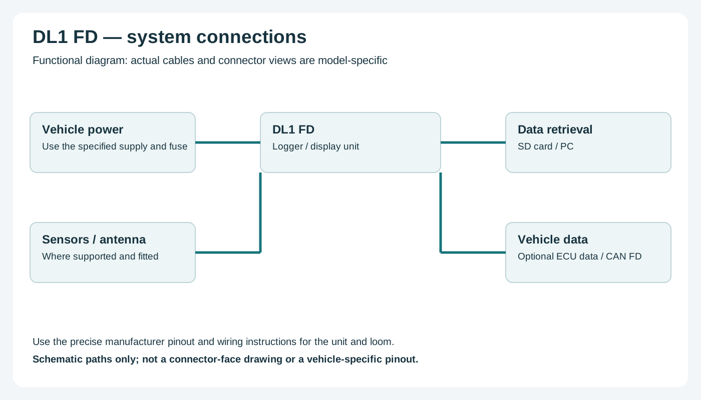
Functional wiring overview; not a connector-face diagram. Confirm actual connections with the manufacturer.
Return to the Race Technology manufacturer page.
Rendered revisions
Open each version to inspect formatting, tables and photographs.
Revision 1: Race Technology DL1 FD
Standalone logger with GPS and inertial sensing, SD storage, analogue and frequency inputs, serial and CAN FD interfaces. GPS output is listed as 5 Hz; higher-rate raw data and sample rates depend on configuration and options.
The manufacturer lists up to 12 analogue inputs, four frequency inputs, CAN FD and legacy CAN. Check optional channels and configured sampling rates on the purchased unit. Manufacturer specifications and documentation.
Pinouts and cabling
The terminal labels include A1–A8 analogue, ground, +12 V supply, low- and high-level RPM inputs and F1–F4 frequency inputs; A9–A12 depend on the option. The low-level RPM input must not be connected directly to an ignition coil. The full numbered data-port pinout has not been verified here.
Check the connector number, version and options on the actual unit against the manufacturer's documentation before wiring. Disconnect power before changing connections.
Wiring overview
Functional wiring overview; not a connector-face diagram. Confirm actual connections with the manufacturer.
Standalone logger with GPS and inertial sensing, SD storage, analogue and frequency inputs, serial and CAN FD interfaces. GPS output is listed as 5 Hz; higher-rate raw data and sample rates depend on configuration and options.
The manufacturer lists up to 12 analogue inputs, four frequency inputs, CAN FD and legacy CAN. Check optional channels and configured sampling rates on the purchased unit. Manufacturer specifications and documentation.
Data analysis software
Stop logging, then open the .RUN file from the DL1 FD’s SD card in Race Technology Analysis to review traces, track maps and lap times. Manufacturer documentation.
Race Technology Analysis example; the available channels and video depend on the recording and enabled options. Image: Race Technology, reproduced with permission; manufacturer source.
The following tables transcribe Race Technology's DL1 FD connector diagram. The diagram depicts the connections on the rear of the unit. Its connector drawings are presented on that rear-panel view; it does not explicitly identify the mating-plug wire-entry view. Check the moulded contact numbers and the unit-specific manual before wiring, because the mating connector is a mirror image when viewed from its mating face. The manufacturer's drawing names the two 12-way connectors DTF13-12PA (A) and DTF13-12PB (B).
12-way connector A
Contact
Manufacturer label
Contact
Manufacturer label
1
A1
7
RPM low
2
A3
8
GND
3
Rx 2
9
CAN2 L
4
CAN2 H
10
Tx 2
5
12 V
11
A4
6
5 V Ref1
12
A2
12-way connector B
Contact
Manufacturer label
Contact
Manufacturer label
1
A5
7
RPM GND
2
A7
8
GND
3
F1
9
F4
4
F3
10
F2
5
RPM high
11
A8
6
5 V Ref2
12
A6
Serial/CAN data connector
The manufacturer labels the following positions on the rear data connector. Positions 4, 6 and 9 are shown without a function label; their assignment has not been verified. The diagram calls position 7 “+V” without specifying its voltage or current rating: confirm both with Race Technology before using it.
Contact
Manufacturer label
1
CAN1 L
2
Rx 1
3
Tx 1
5
GND
7
+V
8
CAN1 H
The manufacturer connection reference describes A1–A8 as analogue inputs and F1–F4 as frequency inputs; optional channels A9–A12 share the F1–F4 positions when that option is fitted. The low-level RPM input must not be connected directly to an ignition coil. Confirm the connector assignments, fitted options and electrical limits for the actual unit before wiring; disconnect power before changing connections.
The manufacturer's sources disagree on supply and sensor-output limits: its connection reference states 10–15 V and 1 A for each 5 V output, while its product specification states 10–23 V and 500 mA per 5 V output. Confirm limits for the exact hardware with Race Technology.
Wiring overview
Functional wiring overview; not a connector-face diagram. Confirm actual connections with the manufacturer.