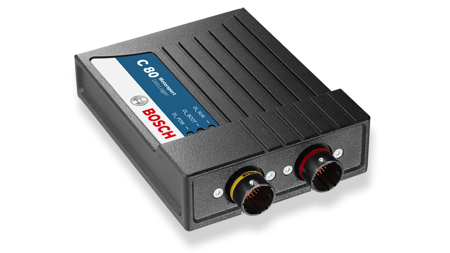
C 80 is offered as a data logger or as a sensor interface with different enabled features. The logger includes a 4 GB first partition, 1,500 channels and 1 ms sampling; 16 GB first partition, second 4 GB partition, DATA_USB, extra input channels and CCP/XCP are options. Interfaces include CAN, Ethernet and RS232. Bosch C 80 product information.
Connector and pinout
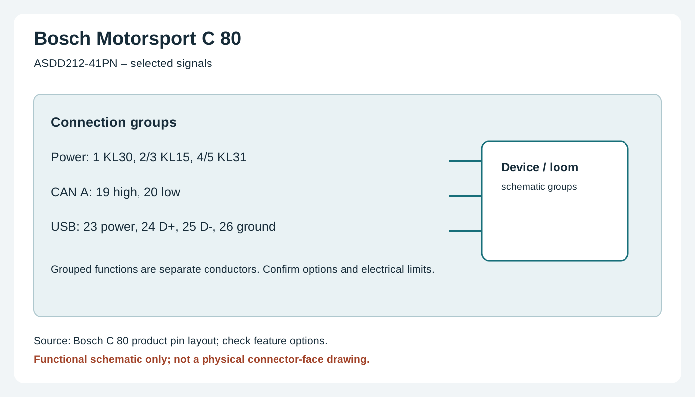
Two 41-position connectors are distinct: device ASDD212-41PN and ASDD212-41PA, mating ASDD612-41SN and ASDD612-41SA. Tables use Bosch's device connector identifiers and cavity numbers; confirm the connector key, view and upgrades from the C 80 pin layout.
ASDD212-41PN
| Pin | Function |
|---|---|
| 1 | KL30 |
| 2 | KL15 |
| 3 | KL15 |
| 4 | KL31 |
| 5 | KL31 |
| 6 | Ethernet 0 TX+ |
| 7 | Ethernet 0 TX− |
| 8 | Ethernet 0 RX+ |
| 9 | Ethernet 0 RX− |
| 10 | Ethernet shield |
| 11 | Ethernet 1 TX+ |
| 12 | Ethernet 1 TX− |
| 13 | Ethernet 1 RX+ |
| 14 | Ethernet 1 RX− |
| 15 | Ethernet 2 TX+ |
| 16 | Ethernet 2 TX− |
| 17 | Ethernet 2 RX+ |
| 18 | Ethernet 2 RX− |
| 19 | CAN A high |
| 20 | CAN A low |
| 21 | CAN B high |
| 22 | CAN B low |
| 23 | USB power |
| 24 | USB data+ |
| 25 | USB data− |
| 26 | USB ground |
| 27 | Sensor power 5V 1 |
| 28 | Sensor ground |
| 29 | Timestamp |
| 30 | Low-side ground 1 |
| 31 | Low-side switch 1 |
| 32 | Low-side switch 2 |
| 33 | Low-side switch 3 |
| 34 | Low-side switch 4 |
| 35 | Low-side ground 2 |
| 36 | Analogue M1 1 |
| 37 | Analogue M1 2 |
| 38 | Analogue M1 3 |
| 39 | Analogue M1 4 |
| 40 | Analogue M1 5 |
| 41 | Analogue M1 6 |
ASDD212-41PA
| Pin | Function |
|---|---|
| 1 | UBATT_FUSE1 |
| 2 | SENSPWR10_1 |
| 3 | SENSPWR5_2 |
| 4 | SENSPWR5_3 |
| 5 | SENSPWR5_4 |
| 6 | Sensor ground |
| 7 | Sensor ground |
| 8 | RS232A TX telemetry |
| 9 | RS232A RX telemetry |
| 10 | RS232B TX GPS |
| 11 | RS232B RX GPS |
| 12 | RS232 ground |
| 13 | REV1_P |
| 14 | REV1_M |
| 15 | REV2_P |
| 16 | REV2_M |
| 17 | REV3_P |
| 18 | REV3_M |
| 19 | REV4_P |
| 20 | REV4_M |
| 21 | Analogue M1 7 |
| 22 | Analogue M1 8 |
| 23 | Analogue M1 9 |
| 24 | Analogue M1 10 |
| 25 | Analogue M1 11 |
| 26 | Analogue M1 12 |
| 27 | Analogue M1 13 |
| 28 | Analogue M1 14 |
| 29 | Analogue M1 15 |
| 30 | Analogue M1 16 |
| 31 | Analogue M2 1 |
| 32 | Analogue M2 2 |
| 33 | Analogue M2 3 |
| 34 | Analogue M2 4 |
| 35 | Analogue M2 5 |
| 36 | Analogue M2 6 |
| 37 | Analogue M2 7 |
| 38 | Analogue M2 8 |
| 39 | Analogue M2 9 |
| 40 | Analogue M2 10 |
| 41 | Lap trigger |
Installation and related information
Confirm the precise model, hardware revision, enabled options and manufacturer's wiring diagram before connecting. Use correct power protection, sensor limits and the chosen ECU protocol; a compatible connector does not guarantee compatible data. Configure in the appropriate Bosch software and verify a short recording or connection. See the Bosch Motorsport manufacturer overview.