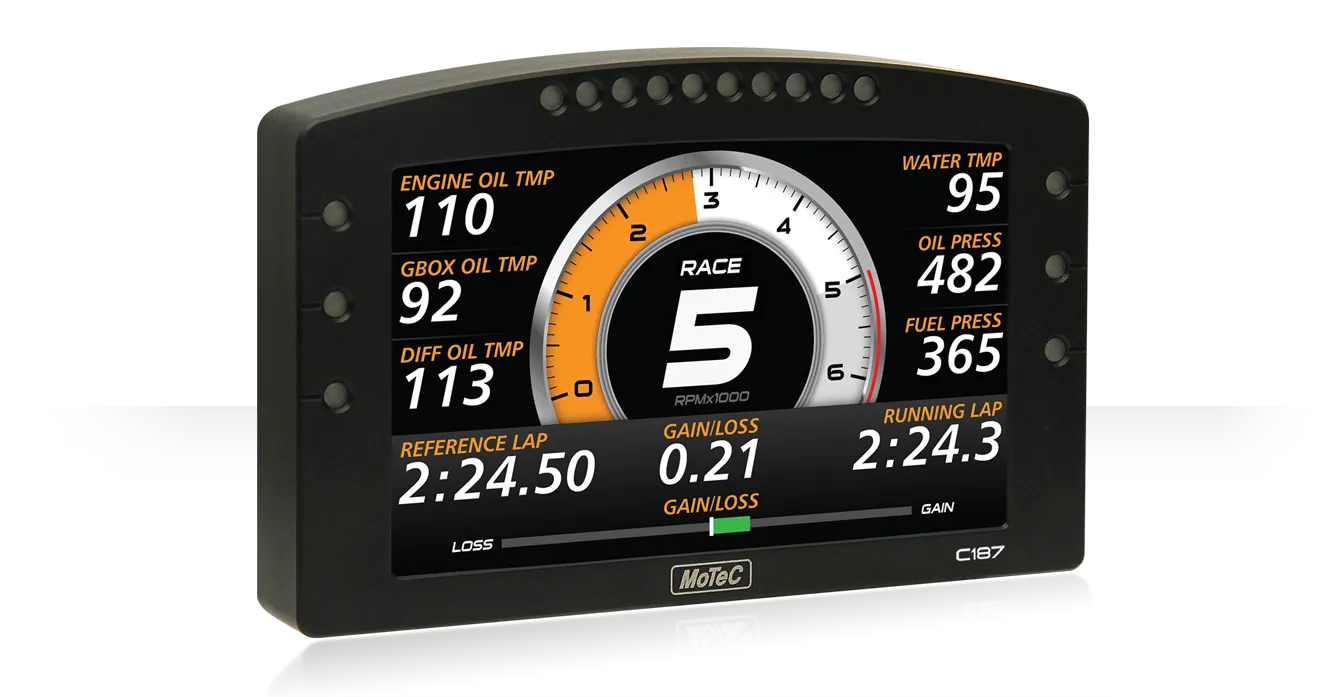
MoTeC C187 (MoTeC part #18072) is a motorsport display and acquisition device. The information here is specific to the cited part; check the label, hardware revision, options and vehicle protocol before connection.
Specifications and options
- 7-inch colour TFT display, 800 × 480 pixels, configurable layouts and programmable channels.
- 250 MB internal logging; USB logging upgrade increases internal storage to 500 MB. Maximum logging rate is 1,000 samples per second.
- Four configurable CAN buses, RS232, ten analogue voltage and four analogue temperature inputs as standard; the 44 I/O upgrade increases those input counts. Features and expansion hardware require configuration.
- MoTeC lists 6–32 V DC operation, i2 analysis and optional T2 telemetry. External GPS and vehicle data require compatible equipment.
MoTeC identifies a previous part #18051; dimensions or construction may differ. Use the document for the unit in hand.
Connector and pinout
79-way (mating connector #68086): the table below follows the manufacturer’s pinout for part #18072. Check cavity numbering and the manufacturer's connector view; the functional map is not a physical connector-face drawing. Blank cells retain the source's unspecified function; do not assign them by assumption. Inputs marked as optional need the appropriate enabled upgrade.
| Pin | Name | Function |
|---|---|---|
| 1 | AV15 | Analogue Voltage Input 15 (with I/O upgrade) |
| 2 | AV16 | Analogue Voltage Input 16 (with I/O upgrade) |
| 3 | AV17 | Analogue Voltage Input 17 (with I/O upgrade) |
| 4 | AV18 | Analogue Voltage Input 18 (with I/O upgrade) |
| 5 | AV19 | Analogue Voltage Input 19 (with I/O upgrade) |
| 6 | 0V | Sensor 0 V |
| 7 | BAT– | Battery Negative |
| 8 | BAT+ | Battery Positive |
| 9 | AUX1 | Auxiliary Output 1 |
| 10 | AUX2 | Auxiliary Output 2 |
| 11 | AUX3 | Auxiliary Output 3 |
| 12 | AUX4 | Auxiliary Output 4 |
| 13 | AUX5 | Auxiliary Output 5 |
| 14 | AUX6 | Auxiliary Output 6 |
| 15 | RS232-2 TX | RS232-2 Transmit Output |
| 16 | RS232-2 RX | RS232-2 Receive Input |
| 17 | 0V | Sensor 0 V |
| 18 | 5V | Sensor 5 V |
| 19 | AV7 | Analogue Voltage Input 7 |
| 20 | AV8 | Analogue Voltage Input 8 |
| 21 | AV9 | Analogue Voltage Input 9 |
| 22 | AV10 | Analogue Voltage Input 10 |
| 23 | AV11 | Analogue Voltage Input 11 (with I/O upgrade) |
| 24 | AV12 | Analogue Voltage Input 12 (with I/O upgrade) |
| 25 | AV13 | Analogue Voltage Input 13 (with I/O upgrade) |
| 26 | AV14 | Analogue Voltage Input 14 (with I/O upgrade) |
| 27 | 0V | Sensor 0 V |
| 28 | 5V | Sensor 5 V |
| 29 | VID1 | Video Input 1 |
| 30 | VID0V | Video 0 V |
| 31 | VID2 | Video Input 2 |
| 32 | VID3 | Video Input 3 |
| 33 | 0V | Sensor 0 V |
| 34 | AT1 | Analogue Temp Input 1 |
| 35 | AT2 | Analogue Temp Input 2 |
| 36 | AT3 | Analogue Temp Input 3 |
| 37 | AT4 | Analogue Temp Input 4 |
| 38 | AT5 | Analogue Temp Input 5 (with I/O upgrade) |
| 39 | AT6 | Analogue Temp Input 6 (with I/O upgrade) |
| 40 | 0V | Sensor 0 V |
| 41 | AT7 | Analogue Temp Input 7 (with I/O upgrade) |
| 42 | AT8 | Analogue Temp Input 8 (with I/O upgrade) |
| 43 | 0V | Sensor 0 V |
| 44 | 5V | Sensor 5 V |
| 45 | AV1 | Analogue Voltage Input 1 |
| 46 | AV2 | Analogue Voltage Input 2 |
| 47 | AV3 | Analogue Voltage Input 3 |
| 48 | AV4 | Analogue Voltage Input 4 |
| 49 | AV5 | Analogue Voltage Input 5 |
| 50 | AV6 | Analogue Voltage Input 6 |
| 51 | 0V | Sensor 0 V |
| 52 | DIG1 | Digital Input 1 |
| 53 | DIG2 | Digital Input 2 |
| 54 | DIG3 | Digital Input 3 |
| 55 | DIG4 | Digital Input 4 |
| 56 | 0V | Sensor 0 V |
| 57 | SW1 | Switch Input 1 |
| 58 | SW2 | Switch Input 2 |
| 59 | CAN4L | CAN 4 Low |
| 60 | CAN4H | CAN 4 High |
| 61 | 0V | Sensor 0 V |
| 62 | 8V | Sensor 8 V |
| 63 | SPD1 | Speed Input 1 |
| 64 | SPD2 | Speed Input 2 |
| 65 | SPD3 | Speed Input 3 |
| 66 | SPD4 | Speed Input 4 |
| 67 | E-TX+ | Ethernet Transmit + |
| 68 | E-TX- | Ethernet Transmit – |
| 69 | AV20 | Analogue Voltage Input 20 (with I/O upgrade) |
| 70 | RS232-1 TX | RS232 Transmit Output |
| 71 | CAN3L | CAN 3 Lo |
| 72 | CAN3H | CAN 3 Hi |
| 73 | CAN1L | CAN 1 Lo |
| 74 | CAN1H | CAN 1 Hi |
| 75 | CAN2L | CAN 2 Lo/RS232 Ground Input |
| 76 | CAN2H | CAN 2 Hi/RS232 Receive Input |
| 77 | E-RX+ | Ethernet Receive + |
| 78 | E-RX– | Ethernet Receive – |
| 79 | RS232-1 RX | RS232 Receive Input |
Wiring and configuration
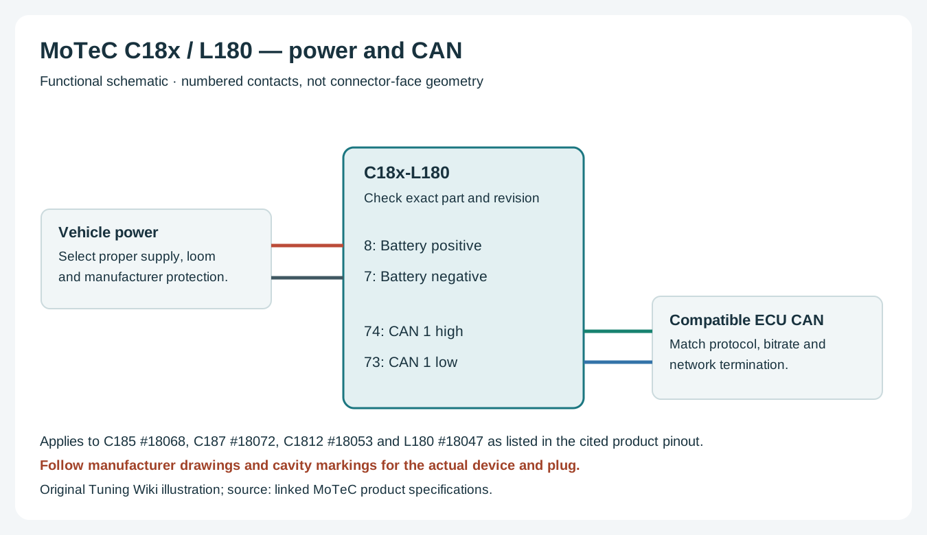
Use the correct connector, power and sensor return for this unit. Match CAN high and low to a compatible, correctly configured network and check existing termination. ECU channels, sensors and lap timing depend on the specific hardware, protocol, configuration and licensed options. Use manufacturer instructions for wire gauge, supply protection and continuity checks; do not connect vehicle battery voltage to a sensor reference output.
MoTeC i2 supports reviewing recorded data; Pro analysis and T2 telemetry require the applicable upgrades. A telemetry licence alone does not provide a radio or cellular connection. See the MoTeC manufacturer guide for family comparisons and references.