Autosport Labs produces RaceCapture in-car data acquisition and telemetry systems and PodiumConnect interfaces for existing data systems. RaceCapture can record locally for later analysis, while supported configurations send selected channels to the Podium online service. The channels, recording and communication hardware depend on the exact model, accessories and configuration.
Model guide
RaceCapture/Track MK4
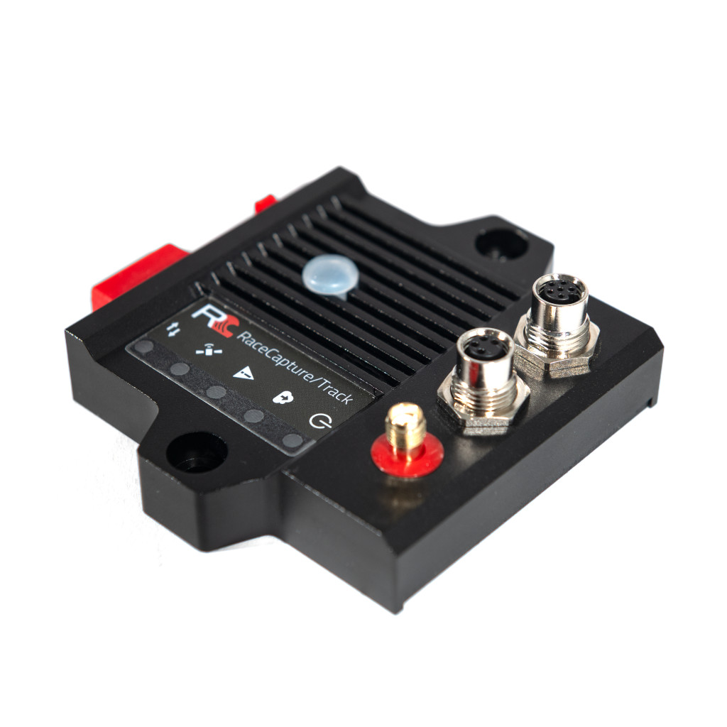
A compact motorsport logger and telemetry system for GPS-based lap analysis and vehicle data. Its manufacturer guide covers automatic recording, CAN/OBD connections, local analysis and live streaming. The RaceCapture app connects to the device for configuration and local dashboard viewing. To send live data to Podium, configure the unit for a 2.4 GHz Wi-Fi hotspot with internet access and enter a device streaming key. Wi-Fi access point mode on its own is a local connection, not an internet uplink.
RaceCapture/Pro MK4
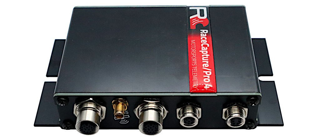
The Pro MK4 is a more sensor-oriented logger with two CAN 2.0 buses, an external GNSS antenna, inertial sensors and microSD storage. Its specification lists eight external 0–5 V analogue inputs plus supply voltage, four digital I/O channels and four timer/RPM inputs. Wi-Fi and Bluetooth are integrated; 4G LTE telemetry is an option. Confirm the unit's fitted hardware, antenna, SIM, plan and regional network support. The documentation lists a maximum 10 Hz cellular telemetry rate, distinct from higher rates supported by sensor inputs; not every recorded channel is necessarily sent at its local rate.
PodiumConnect/Micro
PodiumConnect/Micro is designed to connect an existing data system to Podium. The manufacturer documents one CAN 2.0 bus, software-controlled termination, local recording, and streaming through a supplied-by-user Wi-Fi hotspot; it is not the same as an integrated cellular modem. Its guide provides data-system integration instructions including AiM, MoTeC and VBOX. Check the precise source device, available broadcast channels, cable, GPS data and configuration. Its stated maximum telemetry sample rate is 10 Hz, while local logging can use different rates.
PodiumConnect MK2
The PodiumConnect MK2 is a discontinued earlier interface with two CAN buses and local SD logging. The product page includes cellular specifications and compatible source examples, but its regional modem and network statements differ within the page; confirm the actual fitted variant and current network support before acquiring or using an older unit. The manufacturer suggests Micro or RaceCapture/Track as more modern alternatives.
Expansion and vehicle connections
The AnalogX sensor expander broadcasts four 0–5 V analogue inputs over CAN for a suitably configured receiving device. Raw voltage still needs appropriate scaling or calibration. Autosport Labs publishes a CAN integration guide; check the ECU protocol, bus speed, termination, power, harness, and channel mapping for the actual installation. An OBD-shaped connector or CAN-capable product does not establish that all desired channels are available.
Recording, live telemetry and analysis
RaceCapture app provides configuration, a dashboard and analysis; Podium provides online viewing and session analysis. The app guide describes uploading completed sessions and exporting plain CSV for other tools. The Track MK4 and Micro guides describe short local buffering of telemetry during network interruptions and later upload, subject to configuration. Buffer duration and software behaviour should be verified on the actual system. Distinguish a later upload from a continuous live connection.
Before a session, verify the hardware generation, GPS reception, desired ECU channels, sample rates, recording trigger, local storage, hotspot or cellular coverage, account access and service terms. Make a short test recording and compare it with the remote display. For the wider distinction between local and live systems, see In-car live telemetry and telematics and In-car datalogging and telematics.
Pinouts and cabling

These are model-specific pin numbers as listed in the linked Autosport Labs documentation. The Track and Pro MK4 guides describe female M8 device connectors; the PodiumConnect/Micro pigtail guide illustrates its male plug. Consult the corresponding numbered connector drawing before wiring because viewing the mating cable from the wire side reverses the apparent layout. Confirm wire colours against the actual harness and check continuity with power disconnected.
RaceCapture/Track MK4 and Pro MK4 — M8 power and CAN

The Track MK4 guide and Pro MK4 installation guide list these assignments for their 4-pin CAN1/power and 6-pin CAN1/CAN2/power connectors. Power is specified as 9–24 V; the guides list 1 A (approximately 12 W at 12 V). Use suitable protection and verify the system’s power and connected-device requirements.
| M8 4-pin | Function | M8 6-pin | Function |
|---|---|---|---|
| 1 | CAN 1 low | 1 | CAN 1 low |
| 2 | Power | 2 | CAN 2 low |
| 3 | CAN 1 high | 3 | CAN 2 high |
| 4 | Ground | 4 | Ground |
| — | — | 5 | CAN 1 high |
| — | — | 6 | Power |
For the manufacturer's M8 four-pin pigtail, the colour legend is white CAN low, red power, green CAN high and black ground; do not generalise these colours to other cables. Autosport Labs describes an M8-to-OBD-II adapter for compatible vehicles and a six-pin to dual four-pin splitter for separating CAN1 and CAN2. The harness guide documents extensions, splitters, an inline terminator and the powered dual-CAN hub; a suitable additional power arrangement may be needed for peripherals. Confirm the actual vehicle protocol, channel mapping, supply and network termination rather than relying on the OBD socket shape.
RaceCapture/Pro MK4 — 12-pin M12 sensor connectors
The Pro MK4 has separate 12-pin female M12 connectors for analogue and digital/RPM sensors. The following is the manufacturer's analogue/digital mapping table; select the actual analogue or digital connector and matching harness. The source labels pin 9 “Analog/Digital B” without a further number; its mappings are shown without inventing one.
| Pin | Analogue mapping | Digital mapping |
|---|---|---|
| 1 | Analogue 5 | GPIO 1 |
| 2 | Analogue 6 | GPIO 2 |
| 3 | Analogue 8 | GPIO 4 |
| 4 | Analogue 1 | Timer/RPM 1 |
| 5 | Analogue 2 | Timer/RPM 2 |
| 6 | Vref, 5 V at 0.5 A | Vref, 5 V at 0.5 A |
| 7 | Analogue 3 | Timer/RPM 3 |
| 8 | Analogue 4 | Timer/RPM 4 |
| 9 | Analogue 7 | GPIO 3 |
| 10 | Ground | Ground |
| 11 | Ground | Ground |
| 12 | Ground | Ground |
Analogue inputs and GPIO have different operating limits and configuration; consult the installation guide before connecting a sensor. For a coil-primary RPM source, Autosport Labs recommends a CoilX buffer/filter rather than connecting the noisy high-voltage signal directly.
PodiumConnect/Micro and MK2 integration cable
For PodiumConnect/Micro and the MK2 pigtail, the manufacturer’s M8 4-pin male-plug table assigns 1 CAN low (white), 2 power (red, 9–24 V), 3 CAN high (green) and 4 ground (black). The Micro guide also describes a dedicated AiM five-pin Binder-to-M8 integration cable for the AiM Data Hub. Use the proper compatible adapter and configured CAN mapping; this is not the older MK1’s eight-position Molex connector.
CAN and antenna checks
Match the CAN bitrate and channel mapping to the ECU or data system, verify CAN high and low, and configure termination for the existing network rather than automatically adding another resistor. The manufacturer CAN integration guide describes model-specific termination. Use the correct GPS and, if fitted, cellular antenna for the device and follow its installation guide. Powered hubs, pigtails, ECU interface cables, sensors, data plans and antennas can be separate accessories depending on the kit.
Manufacturer information and product photographs
Autosport Labs product photographs and detailed documentation: RaceCapture/Track product page, RaceCapture/Pro MK4 introduction, PodiumConnect/Micro guide and AnalogX guide. Product imagery is credited to Autosport Labs.