Removed text is struck through; added text is highlighted.
YourDyno supplies instrumentation, software and control components for dynamometers. It can be fitted to new or existing engine, chassis, hub and other test rigs; its data-acquisition box is not itself a roller or power absorber. Dynamometers overview · Manufacturers and suppliers.
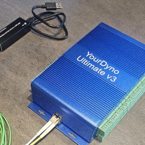
YourDyno Ultimate v3 instrument unit. Image: YourDyno, used with permission.
Company background
According to YourDyno, the brand is owned by Fonneland Engineering AS in Norway, with engineering led by Jostein Fonneland. The manufacturer describes support for dyno builders, original equipment manufacturers and owners retrofitting instrumentation. A founding date is not established by the cited company material and is not assumed here.
Dyno applications and kits
The manufacturer offers kits for inertia, braked chassis, hub and engine dynos, including water-brake and eddy-current applications. A kit is a combination of acquisition electronics and selected sensors or accessories, rather than necessarily a complete mechanical dyno. The chassis brake kit describes speed sensing, load-cell measurement and a separate eddy-brake power supply.
Controllers and software
Standard v4/v5: the installation instructions describe two load-cell and two speed inputs and two brake-control outputs. They describe two units in tandem for four-wheel-drive hub systems, or use of an Ultimate unit.Ultimate v1/v2/v3: a higher-channel-capacity instrument family; the manufacturer's Ultimate instructions describe the hardware generations and installation.Software: the downloads page lists YourDyno and UnaVision software, firmware and manuals. Software and firmware compatibility should be checked for the installed hardware.
Speed and calibrated load-cell signals support torque and power calculations; a separate suitable driver controls an eddy-current brake or valve actuator. Software setup, calibration, correct inertia and machine-specific safety provisions remain necessary. See dynamometer control systems.
Product and version details above are sourced to the maker and were checked 17 November 2026. Confirm current configurations and support before purchasing or modifying equipment.
Hardware capabilities: Standard and UltimateThe following compares the manufacturer's published kit description; connector arrangements, included options, firmware and sensor specifications can differ between revisions. Verify the instructions for the exact unit before buying or rewiring it. Internal converter sampling rates are not the same as guaranteed recorded channel or control-loop rates. YourDyno instrumentation kits.FeatureStandard instrument kitUltimate instrument kit
ApplicationInertia, engine and roller systems with one or two brakes, or 2WD hub systems; two boxes in tandem can support four-brake 4WD hub arrangements.Supports up to four independent brakes, including four-hub installations, when configured with suitable drivers and sensors.
Torque and speedTwo analog load-cell inputs and two digital 0–5 V speed inputs.Four load-cell inputs, six digital 0–5 V frequency/RPM inputs, one variable-reluctance RPM input and one inductive pickup input.
Auxiliary inputsThree 0–5 V analogue channels and one K-type thermocouple input; expansion is available via additional modules or plugins.Eight 0–5 V analogue channels and eight K-type thermocouple inputs; unused load-cell inputs can also be used as auxiliary inputs.
Brake commandsTwo analogue 0–5 V or PWM brake command outputs; the published description also supports one stepper output.Four analogue 0–5 V or PWM brake command outputs; two step/direction actuator outputs are described. Outputs may be shared depending on configuration.
Supply and networkingUSB-powered; CAN support is listed with a separate licence. Check the unit generation and chosen options.External power supply; CAN input and output are listed, subject to supplied hardware and software.The manufacturer quotes 24-bit converters with 30 kHz internal sampling for Ultimate load-cell inputs and 16-bit auxiliary conversion at 1 kHz internal sampling. These numbers describe the electronics, not overall dyno torque accuracy, which depends on load cell, installation and calibration. For Standard digital RPM inputs, a variable-reluctance sensor may require an interface; Ultimate includes a dedicated VR input. Confirm compatibility with the specific hardware version. Manufacturer kit specifications.Brake drivers and what the outputs controlThe instrument box produces control signals; it is not itself a high-current eddy-brake supply or the hydraulic valve. A matched external power stage changes brake-coil current for an eddy-current absorber. For a water or hydraulic brake, a suitable servo or stepper actuator and controller can adjust the valve. The correct electrical input range, power supply, wiring, valve movement and protective limits depend on the equipment. A compatible adapter, driver or replacement sensor may be needed when converting an existing dyno.UnaVision lists eddy-current, water and hydraulic brakes, with generic analogue, PWM and stepper outputs. It also lists configurations for YourDyno eddy-brake power supplies and water valves, plus certain DYNOMITE and SuperFlow water valves. This is a supported interface description, not a guarantee that every model or generation is plug-and-play. Software and brake support; UnaVision software manual.A general speed-hold feedback loop: the control electronics command an appropriate external brake actuator and receive speed feedback. Original schematic for Tuning Wiki, CC BY 4.0; actual YourDyno wiring depends on the installation.Software, test modes and dataYourDyno's UnaVision software describes controlled power sweeps, a load-control sweep, steady target RPM, manual brake demand, target-RPM-versus-time and brake-percentage-versus-RPM curves, and sequences of target RPM and throttle. The brake sweep mode is described for hydraulic and mechanical brake setups. A valid brake driver, usable torque–speed envelope and correct setup are required; software cannot add braking power to an undersized absorber.Runs are saved with their raw data and settings for graphing and comparison. The software describes configurable gauges and alarms, numerical or graphical channels, mathematical channels and weather corrections. Available CAN features include importing channels from compatible aftermarket ECUs, sensor modules and J1939, using DBC configuration, and exporting channels to other devices. OBD adapters, relays and additional sensors require compatible hardware, configuration and, where applicable, licence or plugins. UnaVision capabilities; downloads and manuals.Retrofitting an existing dynamometerYourDyno markets instrumentation for many makes, including Dynojet, Dynocom, DYNOMITE, Froude, Mainline, Mustang, Stuska and SuperFlow. These names indicate the manufacturer's stated application range, not that all generations share connectors or that all existing sensors can be reused. Establish whether the machine is inertia, water, hydraulic or eddy-current loaded; the number and type of brakes; coil ratings or valve actuator details; speed and torque sensor signals; required control and safety functions; and whether existing electronics are retained. YourDyno applications.Configure the correct roller or hub geometry and inertia, load-cell direction and calibration, gear or speed relationship, and each brake channel. Verify calibration, sensor plausibility, safe brake response, limits, stops and emergency arrangements against the dyno and controller manuals before running a vehicle. Compare previous and new measurements only after documenting the correction standard, test procedure and any changes in sensors or calibration.Related comparison: Compare factory and aftermarket dynamometer controllers.
Rendered revisions
Open each version to inspect formatting, tables and photographs.
Revision 1: YourDyno dynamometer controllers
YourDyno supplies instrumentation, software and control components for dynamometers. It can be fitted to new or existing engine, chassis, hub and other test rigs; its data-acquisition box is not itself a roller or power absorber. Dynamometers overview · Manufacturers and suppliers.
YourDyno Ultimate v3 instrument unit. Image: YourDyno, used with permission.
Company background
According to YourDyno, the brand is owned by Fonneland Engineering AS in Norway, with engineering led by Jostein Fonneland. The manufacturer describes support for dyno builders, original equipment manufacturers and owners retrofitting instrumentation. A founding date is not established by the cited company material and is not assumed here.
Dyno applications and kits
The manufacturer offers kits for inertia, braked chassis, hub and engine dynos, including water-brake and eddy-current applications. A kit is a combination of acquisition electronics and selected sensors or accessories, rather than necessarily a complete mechanical dyno. The chassis brake kit describes speed sensing, load-cell measurement and a separate eddy-brake power supply.
Controllers and software
Standard v4/v5: the installation instructions describe two load-cell and two speed inputs and two brake-control outputs. They describe two units in tandem for four-wheel-drive hub systems, or use of an Ultimate unit.
Ultimate v1/v2/v3: a higher-channel-capacity instrument family; the manufacturer's Ultimate instructions describe the hardware generations and installation.
Software: the downloads page lists YourDyno and UnaVision software, firmware and manuals. Software and firmware compatibility should be checked for the installed hardware.
Speed and calibrated load-cell signals support torque and power calculations; a separate suitable driver controls an eddy-current brake or valve actuator. Software setup, calibration, correct inertia and machine-specific safety provisions remain necessary. See dynamometer control systems.
Product and version details above are sourced to the maker and were checked 17 November 2026. Confirm current configurations and support before purchasing or modifying equipment.
Revision 3: YourDyno dynamometer controllers
YourDyno supplies instrumentation, software and control components for dynamometers. It can be fitted to new or existing engine, chassis, hub and other test rigs; its data-acquisition box is not itself a roller or power absorber. Dynamometers overview · Manufacturers and suppliers.
YourDyno Ultimate v3 instrument unit. Image: YourDyno, used with permission.
Company background
According to YourDyno, the brand is owned by Fonneland Engineering AS in Norway, with engineering led by Jostein Fonneland. The manufacturer describes support for dyno builders, original equipment manufacturers and owners retrofitting instrumentation. A founding date is not established by the cited company material and is not assumed here.
Dyno applications and kits
The manufacturer offers kits for inertia, braked chassis, hub and engine dynos, including water-brake and eddy-current applications. A kit is a combination of acquisition electronics and selected sensors or accessories, rather than necessarily a complete mechanical dyno. The chassis brake kit describes speed sensing, load-cell measurement and a separate eddy-brake power supply.
Controllers and software
Standard v4/v5: the installation instructions describe two load-cell and two speed inputs and two brake-control outputs. They describe two units in tandem for four-wheel-drive hub systems, or use of an Ultimate unit.
Ultimate v1/v2/v3: a higher-channel-capacity instrument family; the manufacturer's Ultimate instructions describe the hardware generations and installation.
Software: the downloads page lists YourDyno and UnaVision software, firmware and manuals. Software and firmware compatibility should be checked for the installed hardware.
Speed and calibrated load-cell signals support torque and power calculations; a separate suitable driver controls an eddy-current brake or valve actuator. Software setup, calibration, correct inertia and machine-specific safety provisions remain necessary. See dynamometer control systems.
Product and version details above are sourced to the maker and were checked 17 November 2026. Confirm current configurations and support before purchasing or modifying equipment.
Hardware capabilities: Standard and Ultimate
The following compares the manufacturer's published kit description; connector arrangements, included options, firmware and sensor specifications can differ between revisions. Verify the instructions for the exact unit before buying or rewiring it. Internal converter sampling rates are not the same as guaranteed recorded channel or control-loop rates. YourDyno instrumentation kits.
Feature
Standard instrument kit
Ultimate instrument kit
Application
Inertia, engine and roller systems with one or two brakes, or 2WD hub systems; two boxes in tandem can support four-brake 4WD hub arrangements.
Supports up to four independent brakes, including four-hub installations, when configured with suitable drivers and sensors.
Torque and speed
Two analog load-cell inputs and two digital 0–5 V speed inputs.
Four load-cell inputs, six digital 0–5 V frequency/RPM inputs, one variable-reluctance RPM input and one inductive pickup input.
Auxiliary inputs
Three 0–5 V analogue channels and one K-type thermocouple input; expansion is available via additional modules or plugins.
Eight 0–5 V analogue channels and eight K-type thermocouple inputs; unused load-cell inputs can also be used as auxiliary inputs.
Brake commands
Two analogue 0–5 V or PWM brake command outputs; the published description also supports one stepper output.
Four analogue 0–5 V or PWM brake command outputs; two step/direction actuator outputs are described. Outputs may be shared depending on configuration.
Supply and networking
USB-powered; CAN support is listed with a separate licence. Check the unit generation and chosen options.
External power supply; CAN input and output are listed, subject to supplied hardware and software.
The manufacturer quotes 24-bit converters with 30 kHz internal sampling for Ultimate load-cell inputs and 16-bit auxiliary conversion at 1 kHz internal sampling. These numbers describe the electronics, not overall dyno torque accuracy, which depends on load cell, installation and calibration. For Standard digital RPM inputs, a variable-reluctance sensor may require an interface; Ultimate includes a dedicated VR input. Confirm compatibility with the specific hardware version. Manufacturer kit specifications.
Brake drivers and what the outputs control
The instrument box produces control signals; it is not itself a high-current eddy-brake supply or the hydraulic valve. A matched external power stage changes brake-coil current for an eddy-current absorber. For a water or hydraulic brake, a suitable servo or stepper actuator and controller can adjust the valve. The correct electrical input range, power supply, wiring, valve movement and protective limits depend on the equipment. A compatible adapter, driver or replacement sensor may be needed when converting an existing dyno.
UnaVision lists eddy-current, water and hydraulic brakes, with generic analogue, PWM and stepper outputs. It also lists configurations for YourDyno eddy-brake power supplies and water valves, plus certain DYNOMITE and SuperFlow water valves. This is a supported interface description, not a guarantee that every model or generation is plug-and-play. Software and brake support; UnaVision software manual.
A general speed-hold feedback loop: the control electronics command an appropriate external brake actuator and receive speed feedback. Original schematic for Tuning Wiki, CC BY 4.0; actual YourDyno wiring depends on the installation.
Software, test modes and data
YourDyno's UnaVision software describes controlled power sweeps, a load-control sweep, steady target RPM, manual brake demand, target-RPM-versus-time and brake-percentage-versus-RPM curves, and sequences of target RPM and throttle. The brake sweep mode is described for hydraulic and mechanical brake setups. A valid brake driver, usable torque–speed envelope and correct setup are required; software cannot add braking power to an undersized absorber.
Runs are saved with their raw data and settings for graphing and comparison. The software describes configurable gauges and alarms, numerical or graphical channels, mathematical channels and weather corrections. Available CAN features include importing channels from compatible aftermarket ECUs, sensor modules and J1939, using DBC configuration, and exporting channels to other devices. OBD adapters, relays and additional sensors require compatible hardware, configuration and, where applicable, licence or plugins. UnaVision capabilities; downloads and manuals.
Retrofitting an existing dynamometer
YourDyno markets instrumentation for many makes, including Dynojet, Dynocom, DYNOMITE, Froude, Mainline, Mustang, Stuska and SuperFlow. These names indicate the manufacturer's stated application range, not that all generations share connectors or that all existing sensors can be reused. Establish whether the machine is inertia, water, hydraulic or eddy-current loaded; the number and type of brakes; coil ratings or valve actuator details; speed and torque sensor signals; required control and safety functions; and whether existing electronics are retained. YourDyno applications.
Configure the correct roller or hub geometry and inertia, load-cell direction and calibration, gear or speed relationship, and each brake channel. Verify calibration, sensor plausibility, safe brake response, limits, stops and emergency arrangements against the dyno and controller manuals before running a vehicle. Compare previous and new measurements only after documenting the correction standard, test procedure and any changes in sensors or calibration.