An eddy-current dynamometer applies a controllable resisting torque to a rotating shaft or roller. It is an absorption device: the machine under test supplies the energy, which ultimately becomes heat. It can be fitted to an engine test bed, hub dyno or rolling road. See Dynamometers for the measurement fundamentals.
Principle of operation
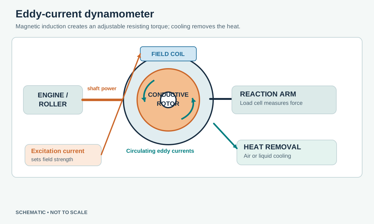
- A shaft drives a conductive rotor through a magnetic field produced by electrical excitation.
- Relative motion induces circulating electrical currents in the conductor. Their own magnetic field opposes the motion that created them, producing a braking torque without friction pads.
- Increasing or reducing excitation changes the magnetic field and therefore the available braking torque, subject to rotor speed, temperature and the absorber's design envelope.
- Electrical resistance converts the currents' energy into heat. Air or a liquid cooling circuit carries that heat away.
An eddy-current absorber does not itself supply drive torque to motor an engine. It cannot provide meaningful eddy-current braking at standstill; available torque varies with speed and is limited by the manufacturer's torque–speed curve. The absorber may be mechanically coupled to a roller by gearing or belt drive, so absorber speed and roller speed are not necessarily equal. Hance, Eddy Current Dynamometer; Magtrol, WB series.
Measurement and control
A common arrangement mounts the absorber casing in bearings so that its reaction force acts through a known-length arm onto a load cell. Force multiplied by the perpendicular arm length gives reaction torque. Speed comes from a shaft or roller pickup; power at that measurement point is torque multiplied by angular speed. During a sweep, inertia and mechanical losses must be accounted for in interpreting total input power; the load cell alone does not automatically capture all acceleration power. Other machines use an in-line torque transducer or a different arrangement. Check the equipment's own measurement model.
The operator can vary field current manually or allow a feedback controller to adjust it. Speed-hold and controlled sweeps permit useful loaded tuning when the absorber has sufficient torque and heat capacity. See Dynamometer Control Systems. A speed-hold setting is not an unlimited brake: below the working envelope the dyno may fail to hold the requested speed.
Cooling, operation and limits
Water-cooled eddy brakes use water to remove heat; the water is not the working fluid producing braking torque as it is in a water brake. Other eddy brakes are air-cooled. Follow the specific machine's continuous and short-duration ratings, cooling flow and temperature limits. Electrical excitation, thermal state, mechanical couplings and calibration all affect the test. Cooling faults and loss of control should be handled using the manufacturer's interlocks and emergency procedures.
Strengths include adjustable non-contact braking and the ability to hold load for mapping within the absorber envelope. Limitations include heat rejection, reduced low-speed capability and the inability to drive the test piece. A combined inertia and eddy-current system uses both stored acceleration energy and controlled absorption; the reporting method must be understood before comparing its power figure with another dyno.
Manufacturer example
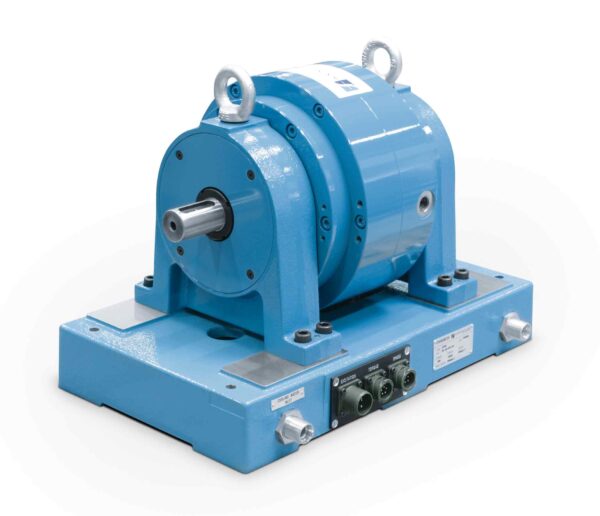
Example manufacturer: Magtrol WB series uses eddy-current loading for motor and engine testing and includes an optical speed sensor. Select the model using its torque–speed and cooling specifications.
Sources
- Hance Dynamometer: Eddy Current Dynamometer — operating sequence, excitation and cooling.
- Magtrol: WB Eddy-Current Dynamometers — example of cooling, speed sensing and rated applications.
- Mustang Advanced Engineering: Engine Dynamometers — examples including air-cooled eddy-current and AC systems.