Connectors covered
The MBE 912 is an early MBE Systems engine-management controller. Its main connector assignments are documented for the 912-C version in a pinout sheet from SBD Motorsport, an MBE specialist and distributor, dated January 2014; a separate SBD wiring instruction for the 912 to 956 series describes a four-way Sure Seal harness interface. This article lists the 15 main-connector positions and the four interface positions. Both are specialist rather than manufacturer documents, so the assignments are graded as suspected, and the 912-C table may not apply to other 912 versions.
912-C main connector
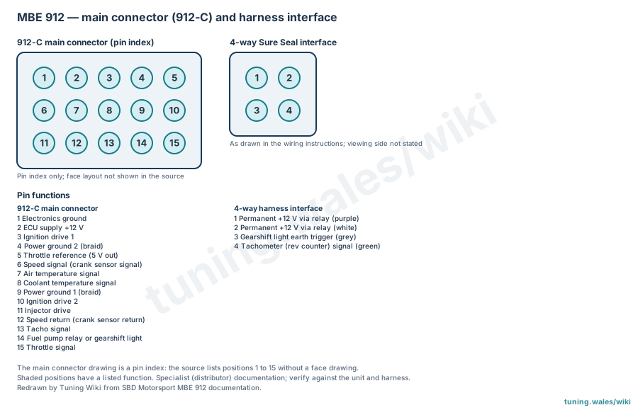
Position 1 is the electronics ground, which also serves as the return for the throttle potentiometer and the coolant and air temperature sensors; positions 4 and 9 are braided power grounds, and position 2 is the ECU +12 V supply. Ignition drives are on 3 and 10 and the injector drive on 11. The crank (speed) sensor connects to 6 (signal) and 12 (return); with a GM sensor its screen goes to 4. Position 5 supplies the 5 V throttle reference and 15 receives the throttle signal; 7 and 8 are the air and coolant temperature signals; 13 is the tacho output and 14 drives the fuel pump relay or a gearshift light. The sheet lists the positions without a face drawing, so the diagram gives them as a pin index.
Harness interface
The four-way Sure Seal interface carries permanent +12 V on pins 1 (purple) and 2 (white), both fed from a relay whose contact is wired directly to the battery positive post with 2.5 mm cable; pin 3 (grey) is the earth trigger for a gearshift light and pin 4 (green) the rev counter signal. The wiring instruction draws the interface face but does not state the viewing side.
Sources
- Connector pin out for 912-C ECU, SBD Motorsport (specialist distributor documentation), January 2014. Accessed 19 November 2026.
- MBE912-956 Series ECU Wiring Instruction, SBD Motorsport (specialist distributor documentation), January 2014. Accessed 19 November 2026.
Connector pinout
MBE 912 standalone ECU: main connector of the 912-C as listed in the SBD Motorsport MBE912 pinout sheet (January 2014), and the four-way Sure Seal harness interface from SBD's 912-956 series wiring instructions (January 2014). Specialist distributor documentation, graded suspected. The 912-C table may not apply to other 912 versions; the main connector face layout is not given, so it is drawn as a pin index. The interface viewing side is not stated.
View orientation is stated beside each photograph. Unknown functions remain in the pin index.
912-C main ECU connector (15 positions)
View: Pin index only; face layout not shown in the source
Select a pin in a photograph or the index to highlight it.
| Pin | Function / cavity | Confidence / source | Notes |
|---|---|---|---|
| Electronics ground Cavity: Populated |
Suspected SBD MBE 912 documentation |
Also the throttle potentiometer, coolant and air temperature sensor return. | |
| ECU supply +12 V Cavity: Populated |
Suspected SBD MBE 912 documentation |
||
| Ignition drive 1 Cavity: Populated |
Suspected SBD MBE 912 documentation |
||
| Power ground 2 (braid) Cavity: Populated |
Suspected SBD MBE 912 documentation |
Also crank sensor screen for a GM sensor. | |
| Throttle reference (5 V out) Cavity: Populated |
Suspected SBD MBE 912 documentation |
||
| Speed signal (crank sensor signal) Cavity: Populated |
Suspected SBD MBE 912 documentation |
||
| Air temperature signal Cavity: Populated |
Suspected SBD MBE 912 documentation |
||
| Coolant temperature signal Cavity: Populated |
Suspected SBD MBE 912 documentation |
||
| Power ground 1 (braid) Cavity: Populated |
Suspected SBD MBE 912 documentation |
||
| Ignition drive 2 Cavity: Populated |
Suspected SBD MBE 912 documentation |
||
| Injector drive Cavity: Populated |
Suspected SBD MBE 912 documentation |
||
| Speed return (crank sensor return) Cavity: Populated |
Suspected SBD MBE 912 documentation |
||
| Tacho signal Cavity: Populated |
Suspected SBD MBE 912 documentation |
||
| Fuel pump relay or gearshift light Cavity: Populated |
Suspected SBD MBE 912 documentation |
||
| Throttle signal Cavity: Populated |
Suspected SBD MBE 912 documentation |
912/956 four-way Sure Seal harness interface
View: As drawn in the wiring instructions; viewing side not stated
Select a pin in a photograph or the index to highlight it.
| Pin | Function / cavity | Confidence / source | Notes |
|---|---|---|---|
| Permanent +12 V via relay (purple) Cavity: Populated |
Suspected SBD MBE 912 documentation |
Relay 87 output; relay 30 wired directly to battery positive with 2.5 mm wire. | |
| Permanent +12 V via relay (white) Cavity: Populated |
Suspected SBD MBE 912 documentation |
Paired with pin 1 from the same relay. | |
| Gearshift light earth trigger (grey) Cavity: Populated |
Suspected SBD MBE 912 documentation |
||
| Tachometer (rev counter) signal (green) Cavity: Populated |
Suspected SBD MBE 912 documentation |