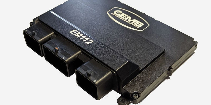
GEMS EM112: An eight-cylinder engine-management system with dual wideband lambda, eight coil drivers, eight programmable peak-and-hold injector drivers, three CAN buses and 256 MB internal logging. Manufacturer source.
Hardware and control
GEMS lists 20 analogue inputs, two differential analogue inputs, twelve timing inputs, two knock inputs and a 112-position Molex connector. It supports electronic throttle, variable cam timing and gearshift control, subject to ECU configuration. GEMS model information.
GEMS systems use GWv4 configuration, with the required ECU definition and licence; software options and custom builds can differ. Record the label, hardware and firmware and confirm connected devices against the matching documentation. GWv4 manual.
Connector and pinout
The EM112 technical specification, 103715 rev 11 includes model-specific connector and pinout drawings. Establish connector view, hardware revision and current limits in that document. The EM112 datasheet's connector C ignition driver names and software codes are internally inconsistent at some positions. Do not resolve them by assumption; obtain a confirmed drawing for the actual build from GEMS before connecting ignition.
Source discrepancies: Rev 11 labels connector A H1 and connector C H1 both as ignition coil driver 4, and assigns repeated software codes to other coil and injector outputs. These values are reproduced as printed, not reconciled; ask GEMS for the confirmed drawing for the unit before wiring. The original diagram includes orientation, current limits and terminal information.
Connector A — black, 32 way
| Pin | Function in rev 11 source |
|---|---|
| A1 | Wideband lambda B 4 |
| B1 | Wideband lambda B 3 |
| C1 | Wideband lambda B heater |
| D1 | PWM low-side driver 7 |
| E1 | PWM low-side driver 8 |
| F1 | Fuel injector driver 5 |
| G1 | Bridge driver A− |
| H1 | Ignition coil driver 4 (O4) |
| A2 | Wideband lambda B 2 |
| B2 | Wideband lambda B 1 |
| C2 | LIN bus |
| D2 | MAP input |
| E2 | Timing input 2 |
| F2 | Fuel injector driver 6 (O26) |
| G2 | Bridge driver A+ |
| H2 | Ignition coil driver 3 (O3) |
| A3 | Knock input B+ |
| B3 | Knock input B− |
| C3 | Timing input 1 |
| D3 | Analogue ground 4 |
| E3 | 5 V sensor supply 3 |
| F3 | Fuel injector driver 7 |
| G3 | Analogue input 20 |
| H3 | Ignition coil driver 5 |
| A4 | Active throttle feedback 2 |
| B4 | Active throttle feedback 1 |
| C4 | Analogue ground 2 |
| D4 | Coolant temperature input |
| E4 | Air inlet temperature input |
| F4 | Fuel injector driver 8 |
| G4 | Power return |
| H4 | Ignition coil driver 6 |
Connector B — brown, 48 way
| Pin | Function in rev 11 source |
|---|---|
| A1 | Ethernet TX+ |
| B1 | Ethernet TX− |
| C1 | Ethernet RX+ |
| D1 | Ethernet RX− |
| E1 | CAN 2 high |
| F1 | CAN 2 low |
| G1 | CAN 1 high |
| H1 | CAN 1 low |
| J1 | CAN 3 high |
| K1 | CAN 3 low |
| L1 | PWM low-side driver 10 |
| M1 | PWM low-side driver 9 |
| A2 | 5 V sensor supply 2 |
| B2 | Timing input 12 |
| C2 | Timing input 11 |
| D2 | Timing input 10 |
| E2 | Timing input 9 |
| F2 | Analogue ground 5 |
| G2 | Timing input 5 |
| H2 | Timing input 6 |
| J2 | 5 V sensor supply 4 |
| K2 | Analogue ground 6 |
| L2 | Secondary 12 V supply |
| M2 | Main relay |
| A3 | Differential analogue input B− |
| B3 | Differential analogue input B+ |
| C3 | Accelerator pedal input 1 |
| D3 | Accelerator pedal input 2 |
| E3 | Lambda input 1 |
| F3 | Lambda input 2 |
| G3 | Analogue input 27 |
| H3 | Analogue input 26 |
| J3 | Analogue input 25 |
| K3 | Analogue input 24 |
| L3 | PWM low-side driver 12 |
| M3 | PWM low-side driver 11 |
| A4 | Differential analogue input A− |
| B4 | Differential analogue input A+ |
| C4 | Bridge driver C+ |
| D4 | Bridge driver C− |
| E4 | Bridge driver D+ |
| F4 | Bridge driver D− |
| G4 | Timing input 7 |
| H4 | Timing input 8 |
| J4 | Analogue input 16 |
| K4 | Analogue input 31 |
| L4 | Power return |
| M4 | Main 12 V supply |
Connector C — grey, 32 way
| Pin | Function in rev 11 source |
|---|---|
| A1 | Wideband lambda A 3 |
| B1 | Wideband lambda A 4 |
| C1 | Wideband lambda A heater |
| D1 | PWM low-side driver 3 |
| E1 | PWM low-side driver 4 |
| F1 | Fuel injector driver 4 |
| G1 | Power return |
| H1 | Ignition coil driver 4 (O2) |
| A2 | Wideband lambda A 1 |
| B2 | Wideband lambda A 2 |
| C2 | Analogue input 23 |
| D2 | MAF input |
| E2 | Timing input 4 |
| F2 | Fuel injector driver 3 (O26) |
| G2 | Main 12 V supply |
| H2 | Ignition coil driver 2 (O2) |
| A3 | Knock input A− |
| B3 | Knock input A+ |
| C3 | Timing input 3 |
| D3 | Analogue ground 3 |
| E3 | 5 V sensor supply 1 |
| F3 | Fuel injector driver 2 |
| G3 | Bridge driver B+ |
| H3 | Ignition coil driver 3 (O1) |
| A4 | Active throttle feedback 4 |
| B4 | Active throttle feedback 3 |
| C4 | Analogue ground 1 |
| D4 | Analogue input 17 |
| E4 | Analogue input 15 |
| F4 | Fuel injector driver 1 |
| G4 | Bridge driver B− |
| H4 | Ignition coil driver 1 (O1) |
Structured pinout
A structured pin index and redrawn diagram of bays A, B and C are in GEMS EM112 connector pinout.
Not established
The microcontroller used in the EM112 is not named in the GEMS technical specification or product page.
Further references
- GEMS EM112 manufacturer source
- Model-specific technical and wiring specification
- GEMS software and downloads
- GEMS manufacturer overview
Sources reviewed 17 November 2026.