Electromotive TECs is a model in the Total Engine Control family. TECs has a dedicated hardware guide; identify the unit before selecting diagrams for TECs200 or other 200-series models. Manufacturer source.
Identification and software
Identify the exact model, serial, firmware and ignition-driver configuration before using a calibration or connecting a loom. WinTEC versions and hardware vary; the Electromotive manual archive separates the generations.
Wiring and pinout
Consult the model-specific manufacturer source and technical archive for the matching connector, firing order, ECU earths, injector drivers and ignition connections. Do not transfer TECgt200 or TECs200 positions to earlier TEC units. Where a complete exact-model pinout has not been verified, use the manufacturer documentation and verify the actual part number.
Availability
As of 17 November 2026, the manufacturer states it is not selling or repairing products. Electromotive notice. See the Electromotive family reference.
Manufacturer connector schedule
The following TECs blue connector schedule is from Electromotive's model-specific installation manual. Functions marked as alternatives depend on configuration; consult the manual for electrical ratings, connector view and harness details. Colours are those listed for the manufacturer's harness.
| Pin | Function | Harness colour |
|---|---|---|
| 1 | Injector or GPO 4 | Yellow/blue |
| 2 | Coil shield | Shield |
| 3 | Fuel pump | Light green |
| 4 | Injector or GPO 3 | Yellow/green |
| 5 | GPIO 1 | White/black |
| 6 | Injector 2 | Yellow/red |
| 7 | GPIO 2 | White/red |
| 8 | GPO 5 / speed | White/green |
| 9 | Coil A | Black |
| 10 | Crank sensor negative and shield | Black / shield |
| 11 | Crank sensor positive | Red |
| 12 | Cam sensor | Tan |
| 13 | Coolant temperature | Grey |
| 14 | Manifold temperature | White |
| 15 | Tach out | Brown |
| 16 | Coil B | Red |
| 17 | Knock | Orange |
| 18 | Sensor ground | Black/white |
| 19 | +5 V | Grey/red |
| 20 | Manifold pressure | Dark green |
| 21 | Throttle position | Dark blue |
| 22 | EGO positive | Purple |
| 23 | Injector 1 | Yellow/black |
Separate two-way power connector
| Pin | Function |
|---|---|
| A | Switched battery +12 V |
| B | Battery ground |
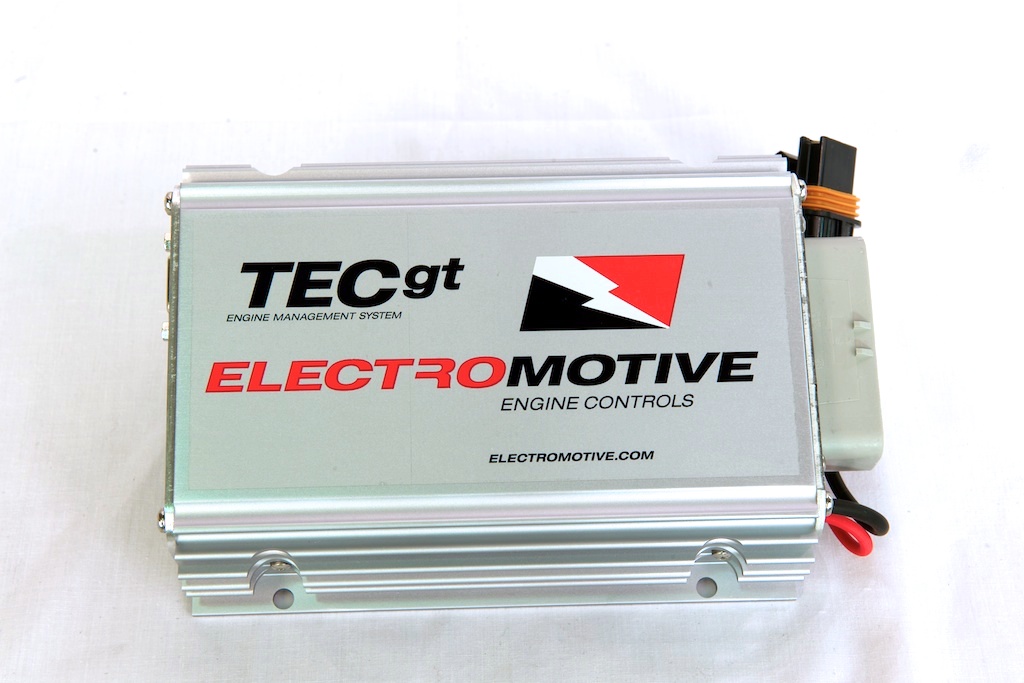
Supported configurations
The manufacturer manual describes TECs as a system for engines of up to four cylinders: 1-, 2-, 3- and 4-cylinder even-fire four-stroke engines with full sequential or phase-sequential injection and waste-spark ignition, and 1- or 2-cylinder two-stroke engines with sequential injection and coil-per-plug ignition. It has up to four fuel channels for high-impedance injectors (each output drives up to two injectors of 12 ohm or more; peak-and-hold injectors are not supported) and up to five general-purpose inputs/outputs; sequential operation needs a cam sensor and reduces the number of general-purpose outputs. The manual refers to the unit's "processors" but does not name the microcontroller. TECs manual.
Connector pinout
Both connectors, with the 23-pin face drawn from the wire side, are given as a structured pin index in Electromotive TECs connector pinout, redrawn from the manufacturer manual.