Removed text is struck through; added text is highlighted.
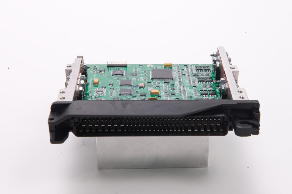
Electromotive TECm. Image: Electromotive, reproduced with permission.
Electromotive TECm is a model in the Total Engine Control family. The manufacturer describes TECm as a replacement motherboard for certain mid-1990s BMW Motronic ECUs; confirm the precise factory ECU and application. Manufacturer source.
Identification and software
Identify the exact model, serial, firmware and ignition-driver configuration before using a calibration or connecting a loom. WinTEC versions and hardware vary; the Electromotive manual archive separates the generations.
Wiring and pinout
Consult the model-specific manufacturer source and technical archive for the matching connector, firing order, ECU earths, injector drivers and ignition connections. Do not transfer TECgt200 or TECs200 positions to earlier TEC units. Where a complete exact-model pinout has not been verified, use the manufacturer documentation and verify the actual part number.
Availability
As of 17 November 2026, the manufacturer states it is not selling or repairing products. Electromotive notice. See the Electromotive family reference.
Factory ECU application
The manufacturer identifies TECm as a replacement motherboard for Bosch Motronic 413 and 506 units, including EWS versions, commonly used with specified BMW M50 and S50 applications. It lists six peak-and-hold injector drivers, full sequential injection and WinTEC4 configuration. Confirm original ECU number, engine and harness before ordering or fitting. TECm product specification.
Manufacturer BMW E36 connector schedule
From section 7.4 of the Electromotive TECm hardware manual. NC is reproduced as the manual’s primary-function label: pins 9 and 10 also list alternate functions, so do not interpret the label as a universal electrical disconnection. Wire colours describe the documented vehicle loom; check the original ECU connector, application and configuration.
All 88 pins of the Motronic harness connector, including pins 54 to 88 not shown in the table above, are listed with functions, alternate functions and loom wire colours in Electromotive TECm connector pinout, redrawn from the manufacturer's hardware manual.
Rendered revisions
Open each version to inspect formatting, tables and photographs.
Revision 5: Electromotive TECmElectromotive TECm. Image: Electromotive, reproduced with permission.
Electromotive TECm is a model in the Total Engine Control family. The manufacturer describes TECm as a replacement motherboard for certain mid-1990s BMW Motronic ECUs; confirm the precise factory ECU and application. Manufacturer source.
Identification and software
Identify the exact model, serial, firmware and ignition-driver configuration before using a calibration or connecting a loom. WinTEC versions and hardware vary; the Electromotive manual archive separates the generations.
Wiring and pinout
Consult the model-specific manufacturer source and technical archive for the matching connector, firing order, ECU earths, injector drivers and ignition connections. Do not transfer TECgt200 or TECs200 positions to earlier TEC units. Where a complete exact-model pinout has not been verified, use the manufacturer documentation and verify the actual part number.
The manufacturer identifies TECm as a replacement motherboard for Bosch Motronic 413 and 506 units, including EWS versions, commonly used with specified BMW M50 and S50 applications. It lists six peak-and-hold injector drivers, full sequential injection and WinTEC4 configuration. Confirm original ECU number, engine and harness before ordering or fitting. TECm product specification.
Manufacturer BMW E36 connector schedule
From section 7.4 of the Electromotive TECm hardware manual. NC is reproduced as the manual’s primary-function label: pins 9 and 10 also list alternate functions, so do not interpret the label as a universal electrical disconnection. Wire colours describe the documented vehicle loom; check the original ECU connector, application and configuration.
Pin
Primary function
Alternate function
Wire colour
1
Fuel pump output
—
Brown/green
2
IAC output (inverted)
PWM GPO
Black/yellow
3
Injector 5 output
—
Brown/green
4
Injector 6 output
—
Brown/violet
5
Injector 4 output
—
Brown/blue
6
Ground
—
Brown
7
Cam timing solenoid
PWM GPO
Green/blue
8
Check engine light output
—
Green
9
NC
PWM GPO
—
10
NC
Analog GPI
—
11
NC
—
—
12
NC
—
—
13
EGO +
—
Yellow
14
Sensor ground
—
Black
15
Ground
—
Black
16
Crank sensor +
—
Yellow
17
Cam sensor +
—
Yellow
18
NC
—
—
19
NC
—
—
20
NC
—
—
21
NC
—
—
22
NC
—
—
23
Coil 4 output
—
Black/blue
24
Coil 6 output
—
Black/violet
25
Coil 5 output
—
Black/green
26
+12 V switched
—
Red
27
ECU relay control
—
Brown
28
Sensor ground
—
Brown/orange
29
IAC output
PWM GPO
Black/green
30
NC
—
—
31
Injector 3 output
—
Brown/yellow
32
Injector 2 output
—
Brown/red
33
Injector 1 output
—
Brown/white
34
Ground
—
Brown
35
NC
—
—
36
Evaporative solenoid output
PWM GPO
Brown
37
NC
—
—
38
O2 sensor heater control
—
Brown/green
39
NC
—
—
40
EGO −
—
Black
41
MAF input
MAP input
Grey/yellow
42
Speed input
On/off GPI
Black/white
43
Crank sensor −
—
Black
44
Sensor ground
—
Brown
45
Shield ground
—
Bare
46
Fuel consumption gauge output
—
White/black
47
Tachometer output
—
Black
48
A/C compressor output
PWM GPO
Black/blue
49
NC
—
—
50
Coil 1 output
—
Black/white
51
Coil 2 output
—
Black/red
52
Coil 3 output
—
Black/yellow
53
NC
—
—
Connector pinout
All 88 pins of the Motronic harness connector, including pins 54 to 88 not shown in the table above, are listed with functions, alternate functions and loom wire colours in Electromotive TECm connector pinout, redrawn from the manufacturer's hardware manual.
Revision 5: Electromotive TECmElectromotive TECm. Image: Electromotive, reproduced with permission.
Electromotive TECm is a model in the Total Engine Control family. The manufacturer describes TECm as a replacement motherboard for certain mid-1990s BMW Motronic ECUs; confirm the precise factory ECU and application. Manufacturer source.
Identification and software
Identify the exact model, serial, firmware and ignition-driver configuration before using a calibration or connecting a loom. WinTEC versions and hardware vary; the Electromotive manual archive separates the generations.
Wiring and pinout
Consult the model-specific manufacturer source and technical archive for the matching connector, firing order, ECU earths, injector drivers and ignition connections. Do not transfer TECgt200 or TECs200 positions to earlier TEC units. Where a complete exact-model pinout has not been verified, use the manufacturer documentation and verify the actual part number.
The manufacturer identifies TECm as a replacement motherboard for Bosch Motronic 413 and 506 units, including EWS versions, commonly used with specified BMW M50 and S50 applications. It lists six peak-and-hold injector drivers, full sequential injection and WinTEC4 configuration. Confirm original ECU number, engine and harness before ordering or fitting. TECm product specification.
Manufacturer BMW E36 connector schedule
From section 7.4 of the Electromotive TECm hardware manual. NC is reproduced as the manual’s primary-function label: pins 9 and 10 also list alternate functions, so do not interpret the label as a universal electrical disconnection. Wire colours describe the documented vehicle loom; check the original ECU connector, application and configuration.
Pin
Primary function
Alternate function
Wire colour
1
Fuel pump output
—
Brown/green
2
IAC output (inverted)
PWM GPO
Black/yellow
3
Injector 5 output
—
Brown/green
4
Injector 6 output
—
Brown/violet
5
Injector 4 output
—
Brown/blue
6
Ground
—
Brown
7
Cam timing solenoid
PWM GPO
Green/blue
8
Check engine light output
—
Green
9
NC
PWM GPO
—
10
NC
Analog GPI
—
11
NC
—
—
12
NC
—
—
13
EGO +
—
Yellow
14
Sensor ground
—
Black
15
Ground
—
Black
16
Crank sensor +
—
Yellow
17
Cam sensor +
—
Yellow
18
NC
—
—
19
NC
—
—
20
NC
—
—
21
NC
—
—
22
NC
—
—
23
Coil 4 output
—
Black/blue
24
Coil 6 output
—
Black/violet
25
Coil 5 output
—
Black/green
26
+12 V switched
—
Red
27
ECU relay control
—
Brown
28
Sensor ground
—
Brown/orange
29
IAC output
PWM GPO
Black/green
30
NC
—
—
31
Injector 3 output
—
Brown/yellow
32
Injector 2 output
—
Brown/red
33
Injector 1 output
—
Brown/white
34
Ground
—
Brown
35
NC
—
—
36
Evaporative solenoid output
PWM GPO
Brown
37
NC
—
—
38
O2 sensor heater control
—
Brown/green
39
NC
—
—
40
EGO −
—
Black
41
MAF input
MAP input
Grey/yellow
42
Speed input
On/off GPI
Black/white
43
Crank sensor −
—
Black
44
Sensor ground
—
Brown
45
Shield ground
—
Bare
46
Fuel consumption gauge output
—
White/black
47
Tachometer output
—
Black
48
A/C compressor output
PWM GPO
Black/blue
49
NC
—
—
50
Coil 1 output
—
Black/white
51
Coil 2 output
—
Black/red
52
Coil 3 output
—
Black/yellow
53
NC
—
—
Connector pinout
All 88 pins of the Motronic harness connector, including pins 54 to 88 not shown in the table above, are listed with functions, alternate functions and loom wire colours in Electromotive TECm connector pinout, redrawn from the manufacturer's hardware manual.