The TurboLamik TCU 2.0 is an external transmission controller for selected ZF 8HP transmissions. The manufacturer states that the original internal TCU is bypassed and a board is installed in the mechatronic assembly, with gearbox commands then handled by the external TCU. It is a distinct hardware product, not an ordinary flash of the factory EGS. TurboLamik product information and product photographs.
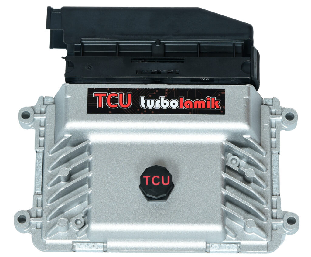
Identification
Identify the unit as TurboLamik TCU 2.0 from its label and supplied documentation, and record its hardware and firmware versions, harness, installed bypass board and calibration. The manufacturer’s download centre lists firmware, TunerPro definitions and gearbox-specific base maps; select files using the supplier’s instructions and the exact installation. The manufacturer product page shows the controller for visual comparison; appearance alone does not establish its internal configuration or compatibility.
Gearbox and ECU compatibility
The supplier's gearbox list names 8HP45, 50, 70, 75, 90 and 95, Audi 8HP55 mechanical and electronic selector versions, and Audi 8HP65 and 8HP90. It lists 8HP51 with an 8HP50 valve plate and 8HP76 with an 8HP75 valve plate. The product page similarly states that 51 and 76 require additional parts. Confirm the complete gearbox and mechatronic part numbers, donor, valve plate, firmware, harness and selector with the manufacturer before modifying or ordering.
The original mechatronic requires modification; see the supplier’s standard 8HP instructions. The Audi 8HP65/95 instructions warn that the 8HP65 connection differs from standard BMW 8HP45/50/70/75 and require additional internal gearbox wiring. These are application-specific and are not interchangeable wiring diagrams.
The supplier maintains a supported ECU list and separate integration instructions. Availability of a CAN protocol is not proof that every ECU firmware, vehicle, shifter or requested torque-control function is compatible. Verify engine data and torque-reduction response in the intended setup.
TCU connector pinout
The following terminal functions are transcribed from the manufacturer’s TCU pinout, updated 19 June 2025. These numbers identify the external controller terminals in that source, not the original BMW EGS or gearbox connector. The online text does not specify a connector-face orientation; use the numbered connector and manufacturer drawing at the source to establish physical cavity position. The source provides the listed functions; this page does not claim independent bench verification. Confirm the pinout and harness against the exact unit and current supplier documentation before applying power.
Battery supply: TurboLamik specifies permanent +12 V on all three terminals 51–53, recommends a 15 A fuse, and warns that disconnecting battery power with ignition may affect park-release behaviour and saving adaptations. Follow its full instructions.
| TCU terminal | Manufacturer function | Notes |
|---|---|---|
| 1–3 | TCU ground | Device ground |
| 4 | A2 clutch input | 0–5 V analog input |
| 5 | A3 | Analog input |
| 6 | A4 throttle position input | Analog input |
| 7 | A5 MAP sensor input | Analog input |
| 8 / 9 | LCD SDA / SCL | Display data / clock |
| 10 | A6 paddles 2 MUX | Analog input; internal 2.2 kΩ pull-up |
| 11 | A7 footbrake input | +12 V signal |
| 12 | A8 | Analog input |
| 13 | A9 handbrake input | Ground signal, internal 10 kΩ pull-up |
| 14 | Oil temperature input | Supplier identifies gearbox plug terminal 1 |
| 15 | A10 program switch | 0–5 V analog input |
| 16 | Sensor ground | Oil temperature sensor ground; supplier identifies gearbox plug terminal 13 |
| 17–20, 24–27 | Sensor ground | External sensor grounds |
| 21 | +9 V output | 0.15 A; speed sensors |
| 22–23 | +12 V output | 0.5 A maximum as listed |
| 28–30 | +5 V output | Consult supplier for load limits |
| 31 | A1 | Analog input |
| 32 | AUX 1 fan relay | 0.5 A |
| 33 | AUX 2 torque reduction | 0.5 A; signal to ECU |
| 34 | AUX output | Low-side, 0.5 A maximum |
| 35 | Ignition +12 V | TCU switch-on signal |
| 36 / 37 | A11 shift up / A12 shift down | Ground input, internal 10 kΩ pull-up |
| 38–42 | AUX outputs | Low-side, 0.5 A maximum |
| 43–45 | Power ground | TCU AUX / solenoid ground |
| 46 | Gear analog output | 0–5 V |
| 47–48 | Analog output | Low-side; manufacturer states 10 mA maximum |
| 50 | Analog out 2 torque reduction | Torque reduction signal to ECU |
| 51–53 | Battery +12 V | Permanent supply; manufacturer specifies 15 A fuse |
| 54 | AUX 9 VSS output | Low-side, 5 A maximum |
| 55 | AUX 10 | Low-side, 5 A maximum |
| 56 | AUX 11 neutral signal | +12 V high-side, 3 A maximum |
| 57 | AUX 12 reverse light | +12 V high-side, 3 A maximum |
| 58–60 | CAN 1 H | Listed individually by manufacturer |
| 61–63 | +5 V output | Supplier specifies 0.5 A combined maximum across these three pins |
| 64 | Universal speed input | |
| 65 | Engine speed input | |
| 66 / 67 | CAN 2 L / H | Engine ECU CAN |
| 68 / 69 | CAN 1 L / H | Gear selector CAN |
| 70 | +12 V output | 0.5 A |
| 71 / 72 | Gearbox speed sensor 2 / 1 | Supplier identifies gearbox plug terminals 10 / 8 respectively |
| 73–75 | Gearbox solenoid ground | Follow model-specific harness instructions |
| 76–79, 81–84, 86–87 | Solenoid outputs | The cited table groups these as outputs; it does not assign individual solenoid functions |
| 88–90 | CAN 1 L | Listed individually by manufacturer |
Terminals 49, 80 and 85 are absent from the cited table; their omission does not establish that they are unused. The listed gearbox connector references are those of the supplier's table, not a universal assignment for every 8HP. The supplier's table refers to gearbox plug terminal 1 both for the oil-temperature input and for solenoid ground; this apparent conflict has not been resolved. Confirm the correct application-specific wiring with TurboLamik before connecting it.
Practical checks
Use the exact manufacturer diagnosis procedure if solenoid errors occur. The supplier notes possible harness, connector or mechatronic-board connection faults. Record fault codes and configuration before making changes; confirm selector and park operation, brake and speed signals, and actual engine torque response using the applicable installation procedure.
See ZF 8HP gearbox controllers and ZF 8HP gearbox types. Manufacturer sources reviewed 17 November 2026; support and firmware may change.
Installation reports and independent guides
Ando Engineering and High Performance Academy’s Volvo 240 build documents a BMW 8HP50, TurboLamik and Haltech Nexus R3. The builder found it easier to fit the internal board on the bench before gearbox installation, and describes adapter, tunnel, crossmember, exhaust and cooler work. On that specific car the team reports using dedicated digital connections for time-sensitive shift requests after finding its CAN-only arrangement too slow. It also changed the clutch-emulator pressure sensor to a range that worked in its software. These are reported solutions for one build, not universal wiring or calibration instructions; follow the supplier’s current documentation for the exact hardware.
A separate S550 Mustang project thread records a gearbox, DCT shifter and modified driveshaft installed with Link ECU and TurboLamik wiring still in progress as of the cited April 2026 update. It identifies adapter and mounting choices, but does not establish the final running or road-test outcome at that point.
Forum and project reports are not independently verified and do not establish compatibility for another engine, gearbox or controller revision.