The Omex 600 series (OMEM600) standalone ECU uses one 36-way loom connector. Its cavities are in three rows, A, B and C, with positions 1 to 12 in each row; the middle row is offset by half a pitch. According to the manufacturer's installation manual, 33 of the 36 cavities carry a function and 11A, 1C and 5C have none listed.
Connector pinout
The connector face is drawn from the wiring-loom side, as in the manual's section 5.3. Power enters at 4A (battery power), and 5A and 7B are chassis earths. 6A is the sensor ground and 9C is the 5 V sensor supply. The crank sensor is at 7A, with its timing ground at 8A. Injection 1 and 2 are at 1B and 2B, and ignition 1 and 2 at 1A and 12A. The four idle-control outputs are at 3C, 2C, 3B and 3A (idle 1 to 4). Auxiliary outputs 1 to 4 are at 4B, 12B, 4C and 2A, and auxiliary inputs 1 to 3 at 10A, 11B and 11C. The pin list gives each loom colour; where a cable has two colours, the manual says the main and tracer colours can be either way round.
The 2v20 manual table cited on the hub agrees for every pin it lists, but it omits the knock-sensor input at 10B, which the 2v01 manual includes. Check the terminal numbering on the actual plug before wiring.
Diagram redrawn by Tuning Wiki from the Omex OMEM600 installation manual.
Sources
- Omex OMEM600 installation manual 2v01, Omex Technology (manufacturer documentation), section 5.3 "ECU Connector", pages 38 and 39; copy hosted as a forum attachment. Accessed 19 November 2026.
- Omex OMEM600 installation manual 2v20, Omex Technology, as cited on the hub; the copy at this address now contains only the first ten pages. Accessed 19 November 2026.
Connector pinout
Omex 600 series (OMEM600) standalone ECU, 36-way loom connector, from the manufacturer's installation manual 2v01 (section 5.3, ECU connector table and loom-side drawing); the 2v20 manual table agrees for every pin it lists. Manufacturer documentation. Cavities 11A, 1C and 5C have no function listed. Loom colours are given in the pin notes; where a cable has two colours, the main and tracer colour can be either way round.
View orientation is stated beside each photograph. Unknown functions remain in the pin index.
ECU loom connector (36-way)
View: Harness plug viewed from the wiring-loom side, as drawn in the manufacturer manual
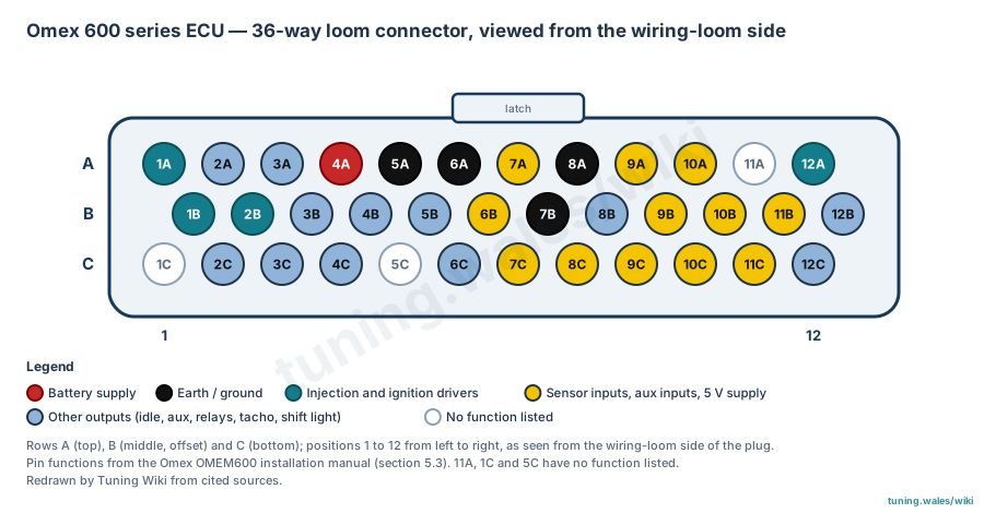
Select a pin in a photograph or the index to highlight it.
| Pin | Function / cavity | Confidence / source | Notes |
|---|---|---|---|
| Ignition 1 Cavity: Populated |
Confirmed Omex OMEM600 installation manual 2v01, section 5.3 |
Loom colour: Violet. | |
| Aux out 4 Cavity: Populated |
Confirmed Omex OMEM600 installation manual 2v01, section 5.3 |
Loom colour: Yellow / violet. | |
| Idle 4 Cavity: Populated |
Confirmed Omex OMEM600 installation manual 2v01, section 5.3 |
Loom colour: Brown / pink. | |
| Battery power Cavity: Populated |
Confirmed Omex OMEM600 installation manual 2v01, section 5.3 |
Loom colour: Red. | |
| Chassis earth 1 Cavity: Populated |
Confirmed Omex OMEM600 installation manual 2v01, section 5.3 |
Loom colour: Black. | |
| Sensor ground Cavity: Populated |
Confirmed Omex OMEM600 installation manual 2v01, section 5.3 |
Loom colour: Grey. | |
| Crank sensor Cavity: Populated |
Confirmed Omex OMEM600 installation manual 2v01, section 5.3 |
Loom colour: Black screened red. | |
| Timing ground Cavity: Populated |
Confirmed Omex OMEM600 installation manual 2v01, section 5.3 |
Loom colour: Blue cables from inside the screened cables. | |
| Coolant temperature sensor Cavity: Populated |
Confirmed Omex OMEM600 installation manual 2v01, section 5.3 |
Loom colour: White / violet. | |
| Aux in 1 Cavity: Populated |
Confirmed Omex OMEM600 installation manual 2v01, section 5.3 |
Loom colour: White / yellow. | |
| Unknown function Cavity: Unknown |
Unknown Omex OMEM600 installation manual 2v01, section 5.3 |
No function listed in the manual. | |
| Ignition 2 Cavity: Populated |
Confirmed Omex OMEM600 installation manual 2v01, section 5.3 |
Loom colour: Yellow. | |
| Injection 1 Cavity: Populated |
Confirmed Omex OMEM600 installation manual 2v01, section 5.3 |
Loom colour: Brown. | |
| Injection 2 Cavity: Populated |
Confirmed Omex OMEM600 installation manual 2v01, section 5.3 |
Loom colour: White. | |
| Idle 3 Cavity: Populated |
Confirmed Omex OMEM600 installation manual 2v01, section 5.3 |
Loom colour: Brown / violet. | |
| Aux out 1 Cavity: Populated |
Confirmed Omex OMEM600 installation manual 2v01, section 5.3 |
Loom colour: Yellow / green. | |
| Fuel pump Cavity: Populated |
Confirmed Omex OMEM600 installation manual 2v01, section 5.3 |
Loom colour: Blue / white. | |
| MAP sensor Cavity: Populated |
Confirmed Omex OMEM600 installation manual 2v01, section 5.3 |
Loom colour: Green. | |
| Chassis earth 2 Cavity: Populated |
Confirmed Omex OMEM600 installation manual 2v01, section 5.3 |
Loom colour: Black. | |
| Shift light Cavity: Populated |
Confirmed Omex OMEM600 installation manual 2v01, section 5.3 |
Loom colour: Blue / grey. | |
| Air temperature sensor Cavity: Populated |
Confirmed Omex OMEM600 installation manual 2v01, section 5.3 |
Loom colour: Green / white. | |
| Knock sensor Cavity: Populated |
Confirmed Omex OMEM600 installation manual 2v01, section 5.3 |
Loom colour: Grey screened. | |
| Aux in 2 Cavity: Populated |
Confirmed Omex OMEM600 installation manual 2v01, section 5.3 |
Loom colour: White / orange. | |
| Aux out 2 Cavity: Populated |
Confirmed Omex OMEM600 installation manual 2v01, section 5.3 |
Loom colour: Yellow / red. | |
| Unknown function Cavity: Unknown |
Unknown Omex OMEM600 installation manual 2v01, section 5.3 |
No function listed in the manual. | |
| Idle 2 Cavity: Populated |
Confirmed Omex OMEM600 installation manual 2v01, section 5.3 |
Loom colour: Brown / orange. | |
| Idle 1 Cavity: Populated |
Confirmed Omex OMEM600 installation manual 2v01, section 5.3 |
Loom colour: Brown / yellow. | |
| Aux out 3 Cavity: Populated |
Confirmed Omex OMEM600 installation manual 2v01, section 5.3 |
Loom colour: Yellow / black. | |
| Unknown function Cavity: Unknown |
Unknown Omex OMEM600 installation manual 2v01, section 5.3 |
No function listed in the manual. | |
| Radiator fan relay Cavity: Populated |
Confirmed Omex OMEM600 installation manual 2v01, section 5.3 |
Loom colour: Blue / black. | |
| Oxygen (lambda) sensor Cavity: Populated |
Confirmed Omex OMEM600 installation manual 2v01, section 5.3 |
Loom colour: White / red. | |
| Throttle position sensor Cavity: Populated |
Confirmed Omex OMEM600 installation manual 2v01, section 5.3 |
Loom colour: Orange. | |
| 5 V sensor supply out Cavity: Populated |
Confirmed Omex OMEM600 installation manual 2v01, section 5.3 |
Loom colour: Pink. | |
| Road speed sensor Cavity: Populated |
Confirmed Omex OMEM600 installation manual 2v01, section 5.3 |
Loom colour: Blue screened red. | |
| Aux in 3 Cavity: Populated |
Confirmed Omex OMEM600 installation manual 2v01, section 5.3 |
Loom colour: White / pin (as printed). | |
| Tacho Cavity: Populated |
Confirmed Omex OMEM600 installation manual 2v01, section 5.3 |
Loom colour: Blue / yellow. |