What the vortices measure
A Karman vortex meter measures volume, not mass. Air in the intake duct is forced past a blunt body, the vortex generator. Downstream of that body the flow sheds a street of vortices, alternating from one side of the wake to the other, the same pattern as the wake of a boat. The rate of shedding follows the speed of the air, and therefore the volume the engine is taking. The control unit counts that rate as a frequency. Faster airflow, higher frequency.
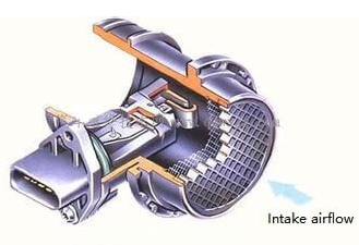
Because the signal is volume, air temperature still has to be measured separately if the control unit is to estimate mass. A hot wire or a hot film has already folded temperature and density into the signal. A Karman meter has not. A change of air-temperature sensor, or a temperature sensor that has drifted, moves the mixture even when the vortex count is perfect.
Optical pickup
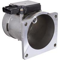
The Toyota optical meter sends the pressure of each vortex to a metal-foil mirror through a small port. The mirror oscillates. A photo-coupler, an LED and a phototransistor, watches the mirror. Each swing interrupts the light, the phototransistor grounds and releases a 5 V line, and the control unit sees a 5 V square wave on the KS terminal. Frequency rises with flow. The frequency is high enough that a DC voltmeter averages the wave and reports a steady mid-scale voltage that does not change with throttle. A frequency meter or an oscilloscope is what shows the flow.
The mirror, the port and the LED are the parts that fail. Oil film on the mirror, or a blocked port, drops the frequency or stops it. The generator itself has no heater and no burn-off. Cleaning a Karman meter as if it were a hot wire does nothing for a dead photo-coupler and can fog the optical path.
Ultrasonic pickup
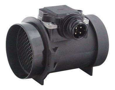
Mitsubishi Electric used the same vortex street and a different transducer. An ultrasonic transmitter and receiver sit across the wake. Each vortex disturbs the sound path, and the electronics turn that disturbance into a square wave whose frequency rises with air speed. There is no mirror and no LED. The meter is still a volume meter, and the control unit still needs air temperature.
This is the meter on a large share of Mitsubishi petrol engines through the 1980s and 1990s, including the engines used in the Eclipse and Talon of that period. The plug and the frequency range belong to the chassis. The Toyota 5 V optical description does not apply here, and neither do the GM hot-film frequencies. Those GM numbers, about 32 Hz at idle on an early Delco film and about 2.9 kHz at idle on a Hitachi 3800, are hot-film signals. A Karman frequency that is merely different from 32 Hz is not a fault.
How to read one
Ignition on, engine running, frequency meter or scope on the signal wire. Frequency must rise as the throttle opens and fall as it closes, smoothly, with no dropouts at one particular speed. A fixed or missing signal can result from the meter, its supply, wiring, signal path or the conditions at its inlet; compare with the vehicle-specific procedure before identifying the fault. Changes to the inlet duct or filter can alter the flow presented to a meter. Confirm the original configuration and investigate modified installations against the applicable system documentation.
A clean, changing waveform does not by itself prove the meter is accurately calibrated or the engine is receiving the correct air and fuel. Check the signal against the specified reference and investigate air leaks, temperature and pressure inputs, fuel supply, sensor calibration and other relevant causes. The optical and ultrasonic meters are not interchangeable with each other or with a mass-air sensor. Replacing one with a hot wire or a film means a new curve in the control unit, the same job as an AFM to MAF conversion.
For the optical Kármán-vortex example and its frequency output, see Toyota Technical Training: engine-control input sensors (independent mirror). Sensor design, supply, output and diagnostic limits must be checked for the particular application.