FuelTech’s ZF 8HP installation board is an internal mechatronic interface used with a FuelTech ECU and a Peak and Hold PRO solenoid driver. It provides external access to the transmission’s solenoids and sensors after the factory controller is removed. The board is not itself a complete standalone transmission controller. The FuelTech product page shows photographs and identifies the product as “8HP Transmissions PCB Install Board”, item 5019100768.

Identification and system architecture
FuelTech supplies the board separately or offers installation into a customer’s original TCU. The manufacturer’s illustrated ZF 8HP manual, version 1.3 shows the board and the opening, soldering and resealing work. Record the exact transmission type, board revision, ECU model, driver and firmware. The operation requires opening and modifying the mechatronics; use the exact manufacturer procedure and qualified installation.
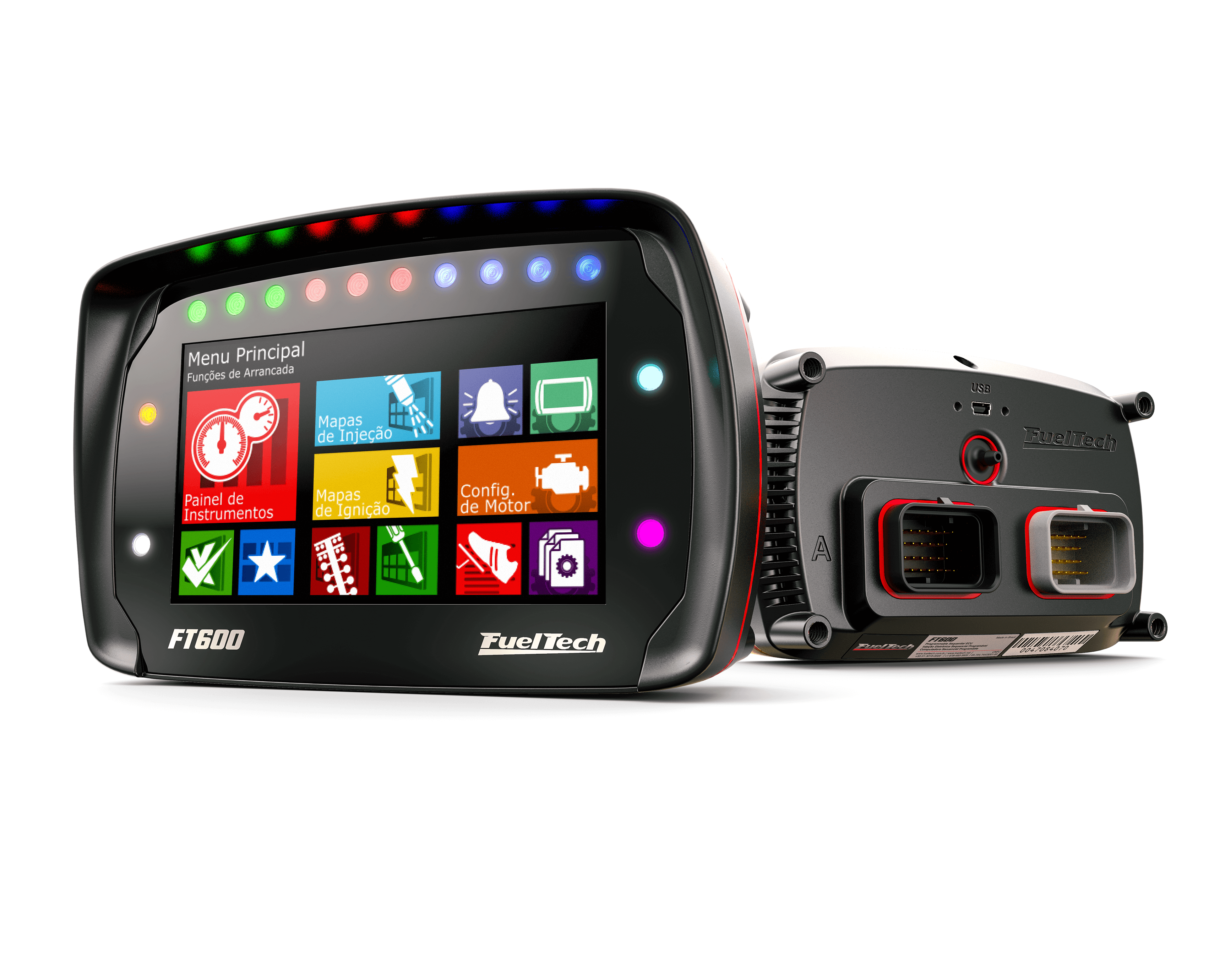
FuelTech specifies a FuelTech ECU and Peak and Hold PRO driver for complete control. Its manual gives a worked FT600 wiring diagram and says three inputs are needed for transmission input-shaft speed, driveshaft speed and temperature; it lists eight control outputs. This does not establish that every FuelTech ECU has sufficient spare inputs and outputs for a particular engine and transmission. Confirm the ECU and driver configuration with FuelTech. See the board product page and manual.
Gearbox compatibility
FuelTech’s version 1.3 manual separates first-generation 8HP45, 8HP70 and 8HP90 from second-generation 8HP50, 8HP75 and 8HP95 in its connector tables. Those are the documented examples below, not a guarantee of interchangeability across every donor, mechatronic, ECU or board revision. Verify the exact transmission and board with FuelTech before purchase or modification. See ZF 8HP gearbox types and the controller overview.
Modified gearbox connector — manufacturer pinout
The following is transcribed from page 4 of FuelTech’s ZF 8HP board manual version 1.3. It describes the gearbox external connector after the FuelTech interface is installed; it is not the original factory-TCU pinout, nor an FT600 ECU connector pinout. The manufacturer’s preceding connector diagram should be used alongside the moulded cavity numbers; it does not clearly label mating-face versus wire-side orientation, so verify orientation and continuity on the actual connector before wiring.
| Gearbox cavity | First generation: 45 / 70 / 90 | Second generation: 50 / 75 / 95 |
|---|---|---|
| 1 | Temperature sensor ground | Temperature sensor ground |
| 2 | Line pressure control | Line pressure control |
| 3 | +12 V input-shaft speed sensor supply | +12 V input-shaft speed sensor supply |
| 4* | Hydraulic accumulator (start/stop) | Hydraulic accumulator (start/stop) |
| 5* | PARK/OFF solenoid | PARK/OFF solenoid |
| 6* | Disable PARK solenoid | Disable PARK solenoid |
| 7 | Clutch C solenoid | Clutch C solenoid |
| 8 | Input-shaft speed sensor, 28 teeth | Input-shaft speed sensor, 28 teeth |
| 9 | Clutch E solenoid | Clutch E solenoid |
| 10 | Driveshaft speed sensor, 40 teeth | Driveshaft speed sensor, 40 teeth |
| 11 | Clutch A solenoid | Clutch A solenoid |
| 12 | Lock-up / torque-converter clutch | Lock-up / torque-converter clutch |
| 13 | Transmission temperature signal | Transmission temperature signal |
| 14 | +12 V solenoid supply | +12 V solenoid supply |
| 15 / 16 | Conflicting source assignments; confirm with FuelTech | See version 1.3 source and confirm for the actual unit |
* FuelTech marks pins 4–6 for the electronic park-lock system only. Its manual specifies a 180 Ω standard sensor pulldown and notes that 200–240 Ω can sometimes be needed; it says resistors from pins 8 and 10 to sensor ground are necessary only for boards older than Rev F. Confirm the installed board revision and sensor configuration against the current manual rather than applying these details universally.
Source discrepancy: An older FuelTech-hosted table lists pin 15 as clutch D and pin 16 as clutch B without distinguishing generations. Version 1.3 reverses these for the first-generation group. Verify gearbox generation, board revision and the actual circuits with FuelTech before connecting pins 15 or 16. Because of the conflict, the first-generation assignments are not presented as verified here; none of the other mappings has been independently electrically tested.
Workshop considerations
The modified system changes the original control and park-lock arrangements. FuelTech’s manual discusses electronic park and a separate racing application; the appropriate arrangement depends on the exact gearbox and intended use. Follow the complete current instructions and verify park, neutral, brake input and shutdown behaviour with the vehicle safely secured before operation. The example FT600 electrical diagram is configuration-specific and should not be transferred to another ECU without checking the required output assignments.
Manufacturer images and references
- FuelTech product page and board photographs — images hosted by and credited to FuelTech.
- FuelTech ZF 8HP installation board manual, version 1.3 — photos, gearbox connector diagram and FT600 wiring example.
- FuelTech manuals index — check for updates before installation.
Sources reviewed 17 November 2026.
Installation reports and independent guides
An enthusiast discussion includes an owner describing an in-progress Lexus project using a supercharged Toyota 3UZ, BMW N63 8HP70, FT600, Peak and Hold PRO and PCB. The owner’s separate project update shows the car being assembled. The posts do not independently establish a completed or reliable transmission installation; do not generalise the commenter’s wider compatibility claims.
Mopar Connection’s 2025 article and linked video discuss the board, FT600 and injector-driver control arrangement, with attention to the required control outputs. This is an independent publication reporting on a product demonstration, not an independent long-term vehicle test. The manufacturer’s current manual and the exact installed board revision remain the authority for wiring and setup.