The Emtron TM16 is a programmable external transmission control module. It can be configured for a ZF 8HP using Emtron's documented 8HP setup. The factory TCM is bypassed in that setup, so it is not interchangeable with systems retaining the unmodified factory controller. Emtron TM16 datasheet and product photograph; Emtron ZF 8HP guide.
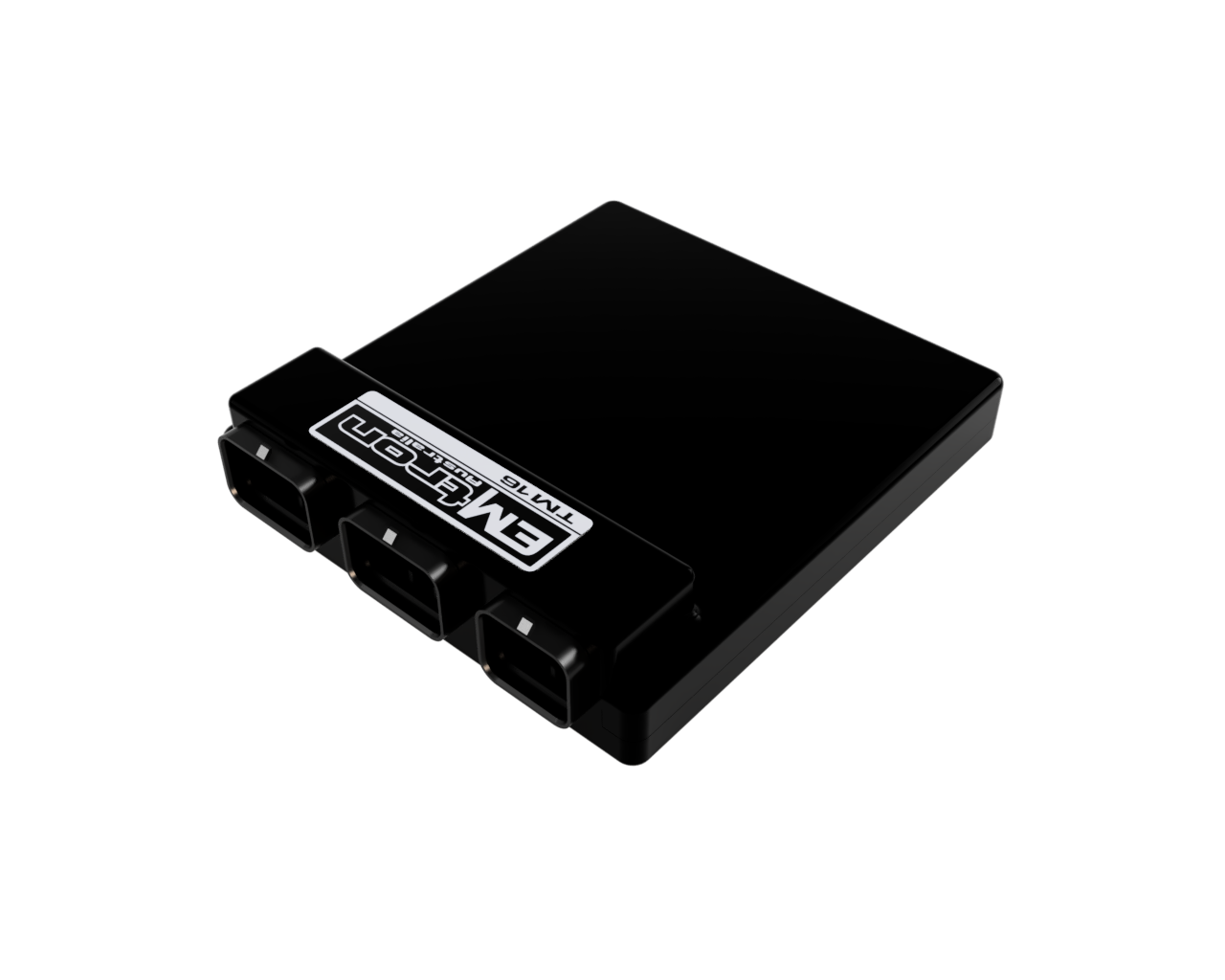
Identification and compatibility
Identify the module as TM16 and record hardware and firmware versions, the transmission plate and mechatronic part numbers, connector and valve-body configuration. The datasheet lists three mating connectors: A 4-1437290-0, B 4-1437290-1 and C 3-1437290-7. TMtune is used for configuration. The 8HP base calibration is based on 8HP70 and is a starting point requiring setup for the actual installation.
Emtron's 8HP guide lists 8HP45, 50, 70, 75, 90 and 95 as supported. It marks 8HP51 and 76 as requiring a Gen 2 valve body. Only gearboxes with 16-pin connectors are supported in this setup; the guide says 10-pin versions lack the necessary inputs and outputs. Confirm the exact assembly and current requirements with Emtron before buying or modifying it.
TM16 controller pinout
The following is the controller-side pin assignment from the Emtron TM16 datasheet, which depicts the view looking into the TCM. Names below are the manufacturer's hardware functions, not fixed 8HP wiring assignments. Use the datasheet connector drawing and power supply guidance for fusing, supply, grounding and output-bank requirements. Inputs and outputs must agree with the actual calibration.
Connector A
| Pin | Function |
|---|---|
| A1 | ANV 1 |
| A2 | ANV 2 |
| A3 | ANV 3 |
| A4 | ANV 4 |
| A5 | ANV 5 |
| A6 | ANV 6 |
| A7 | ANV 7 |
| A8 | ANV 8 |
| A9 | Sensor 0V Ref |
| A10 | ANV 9 |
| A11 | ANV 10 |
| A12 | ANV 11 |
| A13 | ANV 12 |
| A14 | ANV 13 |
| A15 | ANV 14 |
| A16 | ANV 15 |
| A17 | ANV 16 |
| A18 | DI 1 |
| A19 | DI 2 |
| A20 | DI 3 |
| A21 | DI 4 |
| A22 | DI 5 |
| A23 | DI 6 |
| A24 | DI 7 |
| A25 | DI 8 |
| A26 | DI 9 |
| A27 | DI 10 |
| A28 | DI 11 |
| A29 | DI 12 |
| A30 | DI 13 |
| A31 | DI 14 |
| A32 | DI 15 |
| A33 | DI 16 |
| A34 | Sensor 0V Ref |
Connector B
| Pin | Function |
|---|---|
| B1 | Aux 1 |
| B2 | Aux 2 |
| B3 | Aux 3 |
| B4 | Aux 4 |
| B5 | Aux 5 |
| B6 | Aux 6 |
| B7 | Aux 7 |
| B8 | Aux 8 |
| B9 | GND |
| B10 | Solenoid 1 |
| B11 | Solenoid 2 |
| B12 | Solenoid 3 |
| B13 | Solenoid 4 |
| B14 | Solenoid 5 |
| B15 | Solenoid 6 |
| B16 | Solenoid 7 |
| B17 | Solenoid 8 |
| B18 | Solenoid 9 |
| B19 | Solenoid 10 |
| B20 | Solenoid 11 |
| B21 | Solenoid 12 |
| B22 | Solenoid 13 |
| B23 | Solenoid 14 |
| B24 | Solenoid 15 |
| B25 | Solenoid 16 |
| B26 | Analog Out 1 |
| B27 | Analog Out 2 |
| B28 | Analog Out 3 |
| B29 | Analog Out 4 |
| B30 | Solenoid 1-4 Supply Output |
| B31 | Solenoid 5-8 Supply Output |
| B32 | Solenoid 9-12 Supply Output |
| B33 | Solenoid 13-16 Supply Output |
| B34 | GND |
Connector C
| Pin | Function |
|---|---|
| C1 | Battery Hot Supply |
| C2 | Aux 1-4 Supply |
| C3 | Aux 5-8 Supply |
| C4 | Solenoid 1-8 Supply |
| C5 | Solenoid 9-16 Supply |
| C6 | Ignition Switch |
| C7 | GND |
| C8 | CAN 1 Hi |
| C9 | CAN 2 Hi |
| C10 | Hall 1 |
| C11 | Hall 2 |
| C12 | Hall 3 |
| C13 | Hall 4 |
| C14 | CAN 1 Lo |
| C15 | CAN 2 Lo |
| C16 | 5V0 Ref Output 1 |
| C17 | 5V0 Ref Output 2 |
| C18 | 8V0 Ref Output |
| C19 | Sensor 0V Ref |
| C20 | Ethernet Rx+ |
| C21 | Ethernet Rx- |
| C22 | Ethernet Tx+ |
| C23 | Ethernet Tx- |
| C24 | RS232 Rx |
| C25 | RS232 Tx |
| C26 | GND |
8HP-specific wiring and identification
The manufacturer's 8HP instructions show the internal bypass, the transmission connector view, base-calibration wiring and Gen 1/Gen 2 solenoid differences. These connections apply only after the specified mechatronic modifications, not to a standard factory TCU. The source's table labels one Gen 2 entry as pin 17, while its accompanying note says swap pins 15 and 16; confirm the discrepancy with Emtron and the numbered connector before wiring. Do not infer the missing assignment.
Emtron specifies digital inputs rather than the dedicated Hall inputs for the 8HP speed sensors and requires the appropriate pulldown and thresholds. Verify sensor signals, solenoid assignments and current-control calibration for the exact gearbox. The Emtron ECU integration guide documents CAN and engine-torque coordination for its ECU.
See ZF 8HP gearbox controllers and ZF 8HP gearbox types. Sources reviewed 17 November 2026.
Published build examples
Engine Swap Depot's September 2026 feature describes a Mach1 Motorsport BMW E30 with a turbo Mitsubishi 4G63, an adapter, an 8HP70 and an Emtron TM16. The article identifies the parts but does not provide a wiring diagram, calibration or detailed driving assessment; it is a reported build example, not proof that the same package fits another car.
In its 8 October 2026 customer-build feature, Emtron describes the owner of a 2JZ-powered Toyota 86 with an 8HP70 moving to a KV8 engine ECU, TM16 and ED7 display. This is a manufacturer feature describing a conversion in progress, not an independent completed-installation report. Check the individual gearbox, modified mechatronics and engine torque integration against the current Emtron instructions. Sources reviewed 17 November 2026.