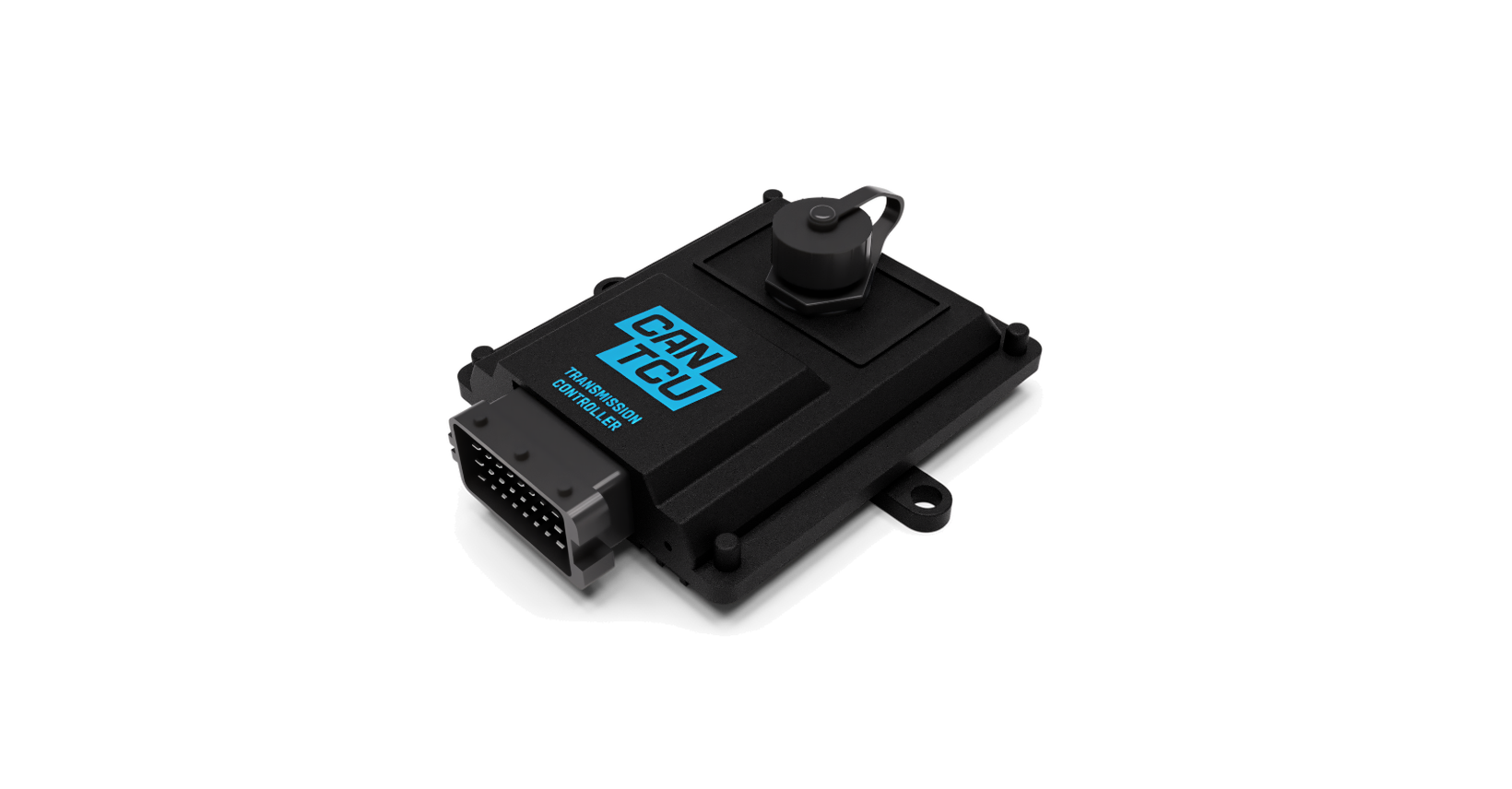
CANformance CANTCU is an external CAN-based transmission controller for selected ZF 8HP applications. CANformance states that its system retains the original transmission control module (TCM); it is not a replacement valve body or direct solenoid driver. Its official product page includes photographs of the controller and package contents. For context see ZF 8HP gearbox controllers and ZF 8HP gearbox types.
Identification
The product is sold as CANTCU Transmission Controller, SKU CANTCU-1. It has a 24-pin Aptiv SICMA connector and a USB-B port under a sealed cap. The supplier lists connector housing 211PC249S0031, large terminal 211CC3S3120 and small terminal 211CC2S2120. Confirm the hardware revision and harness against the supplied unit and diagram; product name alone does not identify firmware or wiring version. The supplier gives an 8–16 V DC input range. Sources: CANformance product page, hardware specifications and pinout notes.
8HP compatibility and software
CANformance’s transmission support matrix distinguishes Race+ from legacy Stock, OEM+ and compatible third-party TCM software. On the page reviewed 17 November 2026, Race+ support was listed for 8HP45, 8HP70 and 8HP90; 8HP50, 8HP75 and 8HP95 F- and G-series support was described as expected with earlier target dates, so actual release should be confirmed with the supplier. Its legacy table listed full support for selected BMW 45/70/90 and 50/75/95 combinations, and beta for BMW G-series 8HP51/76. The matrix also lists specific Dodge, Jaguar, Land Rover, Maserati and Alfa Romeo legacy combinations; some require an initial TCM Tool flash to BMW-based OEM+ software. Check the model, software path and donor rather than assuming a gearbox family is universally supported.
CANformance describes Race+ as software installed on the retained TCM, with live configuration through CANTCU. Its installation manual says to identify and back up the TCM before installing Race+ and to configure Drive and Sport shift maps before driving in those modes. Its legacy procedures and software requirements differ; follow the precise current manufacturer guide.
Controller connector pinout — hardware v1.5
The table transcribes the CANformance 8HP wiring diagram, HW v1.5, dated 10 December 2022. These are CANTCU controller connector cavity labels, not the transmission connector pins. The diagram is a functional wiring schematic, not an oriented connector-face drawing: identify A/B/C cavities using the manufacturer’s connector documentation and moulded markings. Confirm the revision and circuit before connecting power. Do not assume this table applies to another hardware revision.
| CANTCU cavity | Function |
|---|---|
| A1 | VIN — main supply |
| A2 | CAN1 high |
| A3 | CAN1 low |
| A4 | CAN2 high |
| A5 | CAN2 low |
| A6 | CAN3 high |
| A7 | CAN3 low |
| A8 | Ground |
| B1 | Digital output 1 |
| B2 | Analogue input 1 |
| B3 | Analogue input 2 |
| B4 | Analogue input 3 |
| B5 | Analogue input 4 |
| B6 | Digital input 3 |
| B7 | Digital input 4 |
| B8 | Digital output 3 |
| C1 | Digital output 2 |
| C2 | +5 V sensor supply output |
| C3 | LIN |
| C4 | Wake-up output |
| C5 | Digital input 1 |
| C6 | Digital input 2 |
| C7 | Sensor ground |
| C8 | Digital output 4 |
The manufacturer’s pinout notes identify A1/A8 as supply/ground; USB does not power the controller. CAN1 and CAN2 have onboard 120 Ω termination; CAN3 does not. Digital inputs are ground-switching only, and digital outputs are ground-switching with 0.5 A maximum per output. Analogue inputs are 0–5 V. Follow the selected installation diagram for fusing, wake-up, shut-down and wiring gauge. The HW v1.5 diagram shows a 15 A fuse for its combined supply, while the general pinout notes recommend a 10 A fused supply for the controller; these are differently scoped recommendations and must not be applied interchangeably.
Installation and checks
- The controller-to-transmission connector wiring and shifter wiring depend on the selected installation and transmission; use the supplier’s diagram for that combination. Do not transfer transmission cavity numbers from this controller table.
- Use the correct ECU/vehicle integration profile and verify engine data and torque-request behaviour. Follow the installation and initial setup manual for CAN termination, power, diagnostics and first drive checks.
- Read and record hardware and software identifiers and existing fault codes before programming or changing adaptation data. Keep the TCM backup and follow the supplier’s recovery procedure.
Images and source documents
CANformance product photography and product information — images credited to CANformance Engineering and hosted on the manufacturer's website. CANformance 8HP HW v1.5 wiring diagram — manufacturer-hosted technical diagram. Sources reviewed 17 November 2026.
Installation reports and independent guides
These are individual reports, not independently verified compatibility claims. Hardware, firmware and wiring methods vary; compare current CANformance instructions for the actual donor before copying a setup.
- BMW E30 8HP45 build thread: the builder describes CANTCU setup, the shifter and brake signal working on stands on 2 October 2026. In a later 9 October update the builder reports driving it, including engine blips on downshifts. The same thread discusses limited access to the gearbox connector and fill plug in that installation; those details do not establish fitment for other E30 combinations.
- ECUMaster community CAN troubleshooting thread: an installer reports gear selection failing with other CAN devices connected, and uses CAN monitoring to investigate. Switching a steering-wheel terminator on appeared to help that car, but the author still questioned the final bus resistance. Treat this as a diagnostic case, not a recommendation to reproduce its termination; check the full bus topology and device instructions.
- House of Torque standalone harness guide, version 4: the specialist describes its own F-series 8HP loom, shifter, ECU CAN, power, relay and diagnostic connections. It is a commercial, harness-specific guide, not a universal pinout.