A controlled propane enrichment test deliberately adds fuel vapour to a running petrol engine's intake while the technician watches the upstream lambda sensor. If the mixture at that sensor becomes rich, a conventional zirconia switching sensor should move to its high-voltage rich side. This is a response check, not a complete sensor or fuel-system diagnosis.
Safety and scope
Propane is highly flammable. This is a trained-technician workshop test: use a purpose-made, regulated propane enrichment device and follow its instructions and the vehicle manufacturer's procedure. Work in a well-ventilated area with suitable exhaust extraction; keep gas away from ignition sources, hot exhaust components and moving parts. Secure the vehicle, use a gas-tight connection and check for leaks. Never use an open flame or release gas into the workshop. Stop and shut off the gas immediately if there is a leak, backfire, misfire, unstable running or an unsafe condition. Avoid prolonged rich running, which can overheat or damage the catalyst. Do not use this procedure on a diesel engine.
Prepare the test
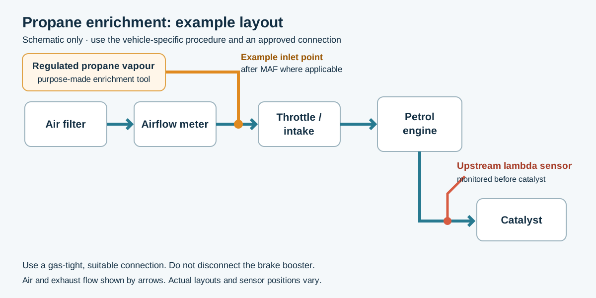
Example layout: introduce regulated propane vapour at a suitable approved intake point. The actual connection depends on the vehicle and test equipment. Diagram created for Tuning Wiki from the sources below; schematic, not a vehicle-specific installation.
- Identify the engine, bank and upstream sensor, and confirm its type and the relevant manufacturer test method. Read fault codes and freeze-frame information; check for misfires, exhaust leaks and heater or wiring faults. Fix conditions that prevent a meaningful test.
- Connect a scan tool to graph the correct upstream sensor, fuel-system status and short-term fuel trim. For a conventional zirconia voltage sensor, an appropriately connected high-impedance oscilloscope gives a clearer, faster trace than a slow scan-tool display. Follow the wiring diagram; do not short or apply voltage to sensor circuits.
- Connect the enrichment device to a suitable intake point specified for the engine and tool, so controlled propane vapour enters the running engine. Where applicable introduce it downstream of the airflow meter; do not disconnect safety-critical brake booster lines. Follow the equipment instructions. Warm the engine and sensor fully and establish stable closed-loop idle, if applicable.
Introduce propane and watch the response

Illustrative trace for a conventional upstream zirconia switching sensor, not a recorded measurement or a wideband voltage specification. Actual timing varies; closed-loop compensation can return the signal to switching during enrichment. Diagram created for Tuning Wiki from the sources below.
- Record the baseline sensor signal, fuel trim and operating state. With the engine running, gradually introduce a small, controlled amount of propane while observing the trace. The added fuel should drive the exhaust mixture toward rich; a hot upstream zirconia switching sensor typically moves toward about 0.8–0.9 V when sufficiently rich. Use the vehicle-specific limit, not this illustrative range, as the acceptance criterion.
- In closed loop the ECU may remove injected petrol in response, bringing the sensor back toward switching and short-term trim negative. A small addition may therefore be compensated before a sustained rich reading appears. If the vehicle and tool procedures permit, increase enrichment only as needed to obtain a clear rich response; do not keep adding gas to force an unstable engine.
- Shut off the propane promptly. Observe the sensor and trim return toward their previous behaviour as the system recovers. Close the cylinder and device valves, remove the equipment safely, restore and check all connections, and verify normal operation.
The published zirconia propane test example describes gradual enrichment and the ECU's ability to compensate. Its timings and limits are an example, not universal specifications. Pico: pre-cat zirconia output and heater explains rich and lean voltage behaviour.
Interpreting the result
- Moves rich: the sensor and its observed signal path respond to this disturbance. That alone does not prove accuracy, response time, heater condition, catalyst health or normal operation across the full range.
- Little or no rich response: first confirm that propane reached the relevant cylinders and made the exhaust genuinely rich, the correct bank and parameter are selected, the sensor is hot, and closed-loop correction has not masked the change. An intake distribution issue, misfire, exhaust leak, wiring, heater, sensor or measurement problem can affect the result. Use vehicle-specific checks before replacing parts.
- After the catalyst: a downstream sensor can respond more slowly because the catalyst stores oxygen. Do not apply an upstream response-time test to it or condemn a catalyst from this test alone.
Wideband and other sensors
Wideband sensors require their ECU or dedicated controller. If the applicable manufacturer permits this disturbance, watch the correctly identified actual lambda or equivalence-ratio parameter: a genuinely rich mixture is lambda below 1, or equivalence ratio above 1. The display may be filtered, clamped or use a different scale. Do not apply the zirconia 0.8–0.9 V rule to a wideband signal or probe its pump-cell wiring as if it were a conventional switching sensor. Titania sensors also use different circuit behaviour. Consult the exact system's data. Pico: Bosch LSU 4.2 wideband testing; Fluke 98 manual, oxygen sensor testing.
See also Lambda sensors: operation, testing and diagnosis, Fuel trims and Fuelling faults.
Sources
- Service manual reproduction: oxygen sensor testing using propane, a specific zirconia test example.
- Pico Technology: pre-cat zirconia sensor; Bosch LSU 4.2 test.
- HSE: vehicle exhaust emissions.