The parts
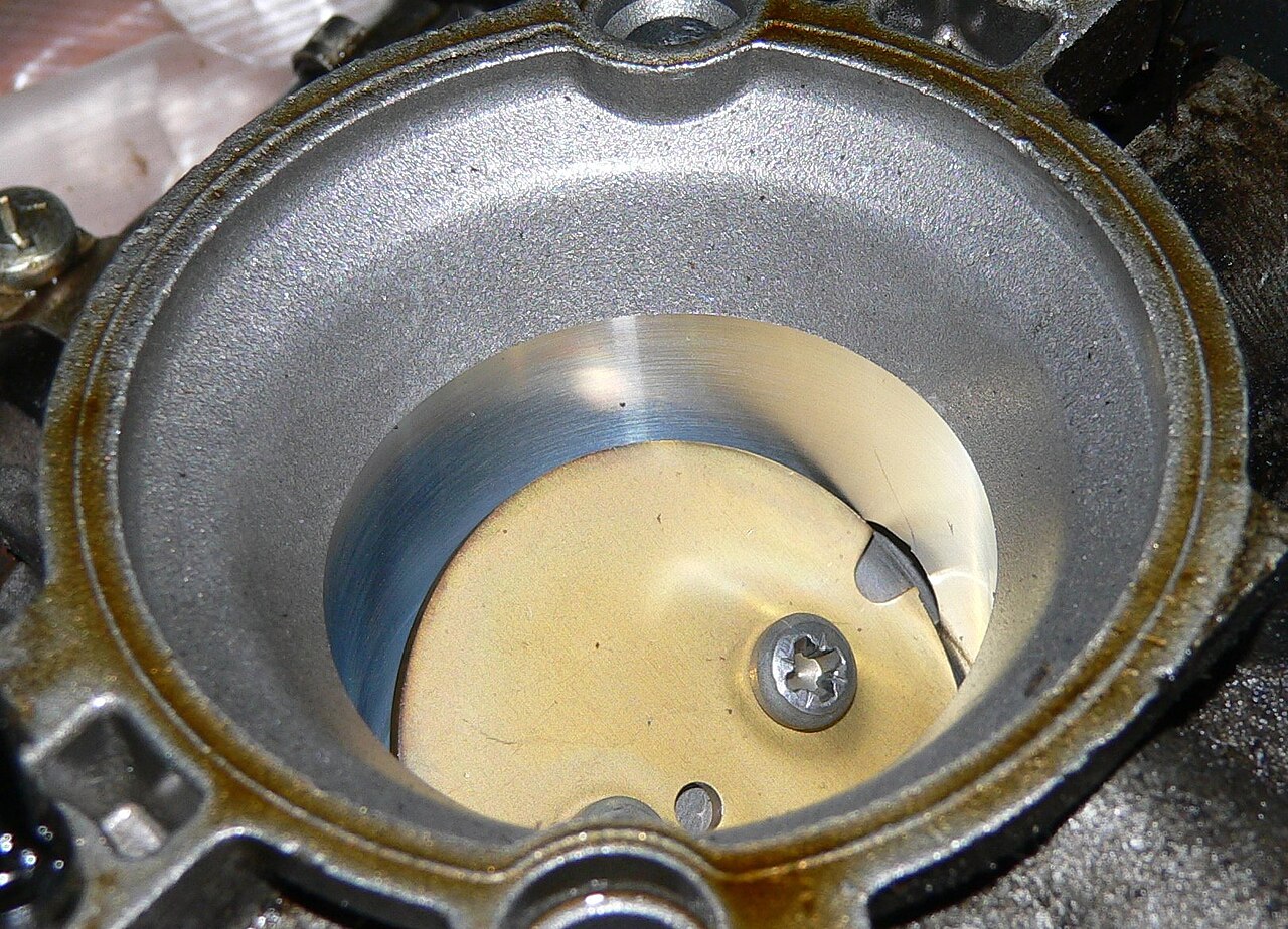

An electronic throttle is three parts. A DC motor drives the throttle plate. Pedal sensors report the driver request. The control unit commands the motor and reads the plate angle back, which closes the loop. Volkswagen Self-Study Programme 210 states that this removes the Bowden cable between the accelerator pedal and the plate.
Motor, gears and position sensor

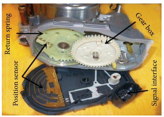
Here the position-sensor tracks are visible in the cover and the motor drives the plate through reduction gears. Other units use contactless sensors, as in the Bosch DV-E/RKL-E description below. Do not infer connector pin functions from the photograph.
For butterfly, slide and barrel valve designs, cable and electronic actuation, individual throttles and Valvetronic, see throttle body.
Bosch Mobility catalogues the passenger-car and light-commercial valve as DV-E/RKL-E. The data sheet lists DV-E5.2/RKL-E5.2, bore 32 to 82 mm, and DV-E5.9(E)/RKL-E5.9(E), bore 32 to 64 mm. Each has a DC motor, a Hall sensor for contactless angle measurement, a gear segment and spring, and the plate. Actuation time t90 is below 100 ms. The interface is analog or SENT. The public sheet does not state a SENT layout, a sensor-supply voltage, or an unpowered rest angle. The control unit moves the plate from the accelerator-pedal position and from other torque requests, including cruise control, adaptive cruise control and the electronic stability programme.
The accelerator-pedal module is the pedal and an angular-position sensor, a potentiometer or a contactless Hall sensor, with an analog or digital output. Bosch states that the request for more or less torque is an input to electronic control of the air charge, and that engine management calculates the required torque from the pedal signal. The page states an idle-voltage tolerance of ±1% and sensor synchronicity below 1.5%. The page does not state the track count or the track voltages.
A Bosch Motorsport electronic throttle body is specified with an accelerator-pedal module and a control unit. Two redundant sensors report plate position. The outputs run in opposite directions across 0 to 90°. The sheet names an idle default position and states that every body has an idle-air position. The sheet does not state the angle. The 2000 DV-E5 information measures response on a Bosch MEx.x control unit and runs its EMC test on a laboratory control unit based on ME7. Bosch ME7 combines this electronic throttle with petrol injection and ignition. Its maps are on ME7 torque, load and boost control. Bosch MG1 and MG1 torque, air, fuel and tuning basics cover the later family.
Throttle position control and PID
The ECU first decides a target plate position from the driver request and other torque demands. A separate, fast position loop compares that target with the measured throttle position and commands the motor. For example, target 30% and actual 24% gives a position error of +6 percentage points. The motor must overcome the return spring and friction in either direction; its H-bridge controls the motor drive. A PID controller is one way of calculating the correction. A pedal-to-target map changes the requested position; it is not the PID map. An idle-speed controller may also request a throttle position, but its RPM-loop gains are not the throttle motor's position-loop gains.
- Proportional (P) responds to the present position error. More gain generally gives a stronger response, but too much can cause overshoot or oscillation.
- Integral (I) accumulates error over time, helping remove a persistent offset such as that caused by spring load. Too much accumulation can make the plate overshoot or hunt. When the motor command is limited or the target is unreachable, accumulated error can wind up; ECUs may limit, reset or condition the integral term.
- Derivative (D) responds to how quickly the error changes and can add damping. It can also amplify noisy position signals, so filtering and the ECU's implementation matter. Some systems use little or no D.
The controller may add feed-forward or bias to compensate for the spring and friction before feedback correction. The Motorsport Electronics DBW guide explains spring and friction compensation and output limits for its system. Limits, sample time, filtering, gain units, sensor scaling and even whether an “I” setting is a gain or a time constant differ between controllers. Values cannot safely be copied between ECUs or throttle bodies.
Example PID gain maps
Teaching illustrations only: invented values, not a validated calibration or starting tune. HP Tuners documents P and I tables indexed by throttle position and position error for its CORE ECU. The examples below show that kind of two-axis layout for positive errors only; actual breakpoints, negative-error coverage, interpolation, units and limits must follow the ECU definition. They are not published CORE settings.
Illustrative P gain — rows: position error in percentage points; columns: measured throttle position (%).
| Error / position | 10% | 50% | 90% |
|---|---|---|---|
| 2 | 2.0 | 2.0 | 1.5 |
| 6 | 3.0 | 3.0 | 2.5 |
| 12 | 4.0 | 3.5 | 3.0 |
Using HP Tuners' stated P calculation solely to demonstrate lookup arithmetic, at 50% measured position and +6 percentage points error, the illustrative cell 3.0 gives a P term of 18% before limits and the other terms. This is not a predicted final PWM duty.
Illustrative I gain — same axes; values in %/s under the CORE convention, only for explaining the lookup.
| Error / position | 10% | 50% | 90% |
|---|---|---|---|
| 2 | 10 | 10 | 8 |
| 6 | 12 | 12 | 10 |
| 12 | 8 | 8 | 6 |
At 50% position and +6 points error, the cell is 12%/s. In the documented CORE calculation with a 0.0001 s task time, the increment is 6% × 0.12/s × 0.0001 s = 0.000072 percentage points for that cycle, before any limits or enable conditions. Other ECUs may schedule gains differently or use fixed gains instead of maps. These numbers imply no preferred gain shape. D, feed-forward and output limits are also controller-specific.
Checking response
Use the ECU supplier's procedure and a known compatible base configuration. With the engine off, secure the vehicle, keep hands and objects clear of the moving plate, and log target and both position tracks, position error, motor command, supply voltage and faults. Check that commanded movement is in the correct direction, tracks agree according to their specified relationship, and small and larger target changes settle promptly without sustained oscillation or excessive overshoot. An apparently fast response that trips a tracking fault is not a satisfactory tune. The Motorsport Electronics test sequence verifies sensors and motor direction before closed-loop tuning. Diagnose binding, wiring, poor voltage and calibration before changing gains; retain the ECU's safety checks and fail-safe strategy.
An ME7.1.1 production size difference
Volkswagen's W8 engine-management self-study programme 249 describes its W8 ME7.1.1 throttle module as having a larger air-intake throat than the similar VR6 module and states that the W8 version has no throttle-heating connection. The programme does not give bore sizes or part numbers here. It is evidence that related-looking production modules can differ, not evidence that a W8 throttle is a compatible VR6 or S4 upgrade.
For the same W8 example, VW describes a restricted output if one angle sensor fails, while failure of both disables the throttle drive and leaves an increased idle speed. These responses and the heating arrangement must not be assumed for other hardware. Check the exact vehicle and part documentation; the ME7.1 M-box throttle reference discusses selection, adaptation and airflow-model checks.
Torque request and the charge path
The control unit reads the pedal as a torque request and then selects a plate angle. Programme 210 describes that order for Volkswagen electronic power control and splits the actuators. Throttle angle, and charge pressure on a turbocharged engine, are the variables for long-term torque demand. That is the charge path, and it is the slower of the two paths in the programme: the short-term path is the ignition point, injection time and cylinder suppression, and the programme describes it as independent of charge. Actual torque in the programme comes from engine speed, the load signal and ignition advance. The plate can move with the pedal released. Idle-speed control, catalytic-converter heating, limiters, lambda control, the gearbox, traction control, engine-braking control and the air-conditioning compressor are further torque demands in that account. How much air entered is airflow metering. The ignition point on the short-term path is ignition timing.
Valvetronic exception: on BMW’s N62, variable intake-valve lift largely controls normal engine load, while an electronic throttle remains for functions including some starting conditions, intake vacuum and backup. The details are engine-specific; see throttle body and Valvetronic and the BMW N62 service information.
Redundant signals and emergency running
Pedal position and plate position are each measured twice, so one signal can be tested against the other.
Programme 210 fits potentiometers G79 and G185 on one pedal shaft. Each has its own 5 V supply, earth and signal. A series resistor in G185 gives the senders different characteristics, which the programme requires for the safety and test functions. The tracks move together, on unequal spans. In display group 062 the positions are a percentage of 5 V, and the programme states that 100% equals 5 V.
One failed pedal sender stores a fault, lights the electronic-power-control lamp and selects idle. If the remaining sender is at idle within a defined test period, driving resumes. A full-throttle request raises engine speed slowly. Cruise control and engine-braking moment control stay off, and idle is also taken from the brake-light switch or the brake-pedal switch. Both pedal senders failed leaves a higher idling speed, 1500 rpm maximum, and engine speed stays there as the pedal moves. A simultaneous loss of both senders can leave the lamp off, depending on the engine management system. The term substitute function appears where the programme states that the clutch-pedal switch has no substitute function.
Angle senders G187 and G188 share supply and earth, with one signal wire each. Inverse curves let the control unit tell them apart. One failed angle sender lights the lamp and switches off torque subsystems such as cruise control. Pedal response continues, and the remaining sender is checked against the load signal. Both angle senders failed switches the drive off. Engine speed stays at 1500 rpm while the pedal moves. With the drive de-energised, the spring return sets the emergency running position. Limited driving remains at a higher idling speed, on the emergency-running functions only. The 1500 rpm figure belongs to the failed-sender cases.
The Bosch Motorsport MS 7.8 manual states that its fault responses can differ from series-production electronic throttle control. A pedal fault makes electronic throttle control inactive. Inverted sensor wiring or inverted actuator wiring is the usual cause. The pedal check is a two-to-one ratio, so those tracks move together. The throttle check is a sum to 5 V, with the main track rising and the redundant track falling. Swapped throttle wires can still meet the sum. The direction test assigns each wire to one input. Calibration codeword 4 is “calibrate limp home position”, beside the lower and upper mechanical stops. The manual does not state the angle.
Idle default position
DV-E5 technical customer information Y 289 K00 025 calls the unpowered rest position the idle default position, Notluftpunkt (NLP). It lies above the lower mechanical stop. On electrical disconnection the plate falls back to it. The airflow test places the plate there with the return spring, the Rückstellfeder, from the upper mechanical stop. The standard NLP angle is 5°. The nominal angle may be shifted for an application, and customer-specific variants exist. The design is stated to observe FMVSS 124 as of 25 April 1996 when that position stays in the idle range. On an MEx.x control unit at 13.5 V ± 0.5 V, powered travel from 0% to 100% and from 100% to 0% has t90 at or below 100 ms. Currentless return from wide open to the NLP has t90 at or below 300 ms.
At a pressure drop of 60 kPa ± 2.5 kPa, 100 kPa ambient, 40% relative humidity and 24°C, new-part NLP flow for a 60 mm plate is 9.7 g/s ± 1.17 g/s. The German text says dirt remaining after the bore is cleaned can lower a used body by up to 2 kg/h. Programme 210 defines a lower electrical stop in the control unit, just above the lower mechanical stop, and in operation the plate closes to that electrical stop so it stays clear of the housing. The current DV-E/RKL-E sheet publishes idle air leakage as a separate line: under 2.5 kg/h for DV-E5.2 and under 2.3 kg/h for DV-E5.9(E), each for a 57 mm bore. The sheet does not state an angle or a pressure drop for that line. It includes a spring, and it does not state a rest angle. The Motorsport idle default position is likewise given without an angle.
Learning the throttle stops
The ECU needs to relate each throttle-position sensor signal to the plate's usable travel. Bodies, sensors and mechanical tolerances differ. During the applicable calibration or basic setting, an ECU may move the plate through positions and store or check sensor values at its stops and, where supported, the spring-return position. The details, limits and whether adaptation is automatic depend on the ECU. Haltech's DBW calibration, for example, automatically moves each enabled throttle through positions and calibrates the accelerator pedal separately.
- Lower mechanical stop: the physical closed end of travel. On VW's SSP 210 system, the lower electrical stop is set just above it in operation so the plate does not continually strike the housing.
- Upper mechanical stop: the physical open end of travel. The ECU may use a calibrated usable range inside the physical limits.
- Default or limp-home position: the spring-return position when the motor is not energised; it lies above the lower mechanical stop on the Bosch DV-E5 described below. It is not automatically the learned closed position or the commanded idle angle.
As a simple illustration, if one sensor reads 0.50 V at a learned lower reference and 4.50 V at its upper reference, 2.50 V is halfway between those reference voltages. The second track must be checked independently against its expected direction and range; this example is not a universal voltage specification. A position learn identifies travel and sensor references; it does not by itself tune PID, prove airflow-model compatibility, or repair a sticking plate, wiring fault or worn sensor.
When and how to relearn
Check the vehicle's repair information after throttle-body, ECU or engine replacement and after cleaning or other work that calls for adaptation. Some vehicles require it after battery disconnection; others have different rules. Before starting, check for relevant faults, a clean and free-moving mechanism, sound wiring and a stable supply. Keep clear of the plate because it can move without pedal input. Do not adjust factory stop screws or force the plate against its stops; Bosch's DV-E5 limit for lower-stop learning is 20°/s and its data warns against driving dynamically into the stops.
As one documented example, Ross-Tech's VW/Audi throttle-body alignment guide calls for ignition on, engine off, foot off the pedal and suitable voltage and temperature. Applicable systems use the controller-specific Basic Settings procedure; some use group 060 and newer UDS controllers use a named function. The throttle cycles while the procedure runs. Confirm the tool reports completion, then check faults and sensor readings; an error is not a completed learn. Conditions and steps vary by vehicle, so follow its repair procedure rather than assuming group 060 or an ignition cycle works everywhere. The Land Rover example below uses a different sequence.
Land Rover ME7.2 adaptation example
In the Land Rover engine-management training manual, pages 180–181, a Bosch ME7.2 electric throttle uses two integrated potentiometers. The manual describes comparing the two signals against an air-mass-based plausibility estimate when they disagree; if no plausible throttle position can be established, the described strategy switches off the motor and activates injection cut-out. This is the documented Land Rover implementation, not a universal ME7 fault response.
For replacement of that throttle, the same manual describes clearing the old adaptation using TestBook/T4, switching the ignition off for 10 seconds, then turning it on while the unit learns. It describes a different case after ECM replacement, where no previous throttle adaptations have been established. Follow the exact vehicle's current repair procedure and verify completion and fault status: this Land Rover sequence is not a substitute for VW/Audi group 060, and a successful position learn alone does not prove the replacement's airflow model or electrical compatibility.
Cable throttle
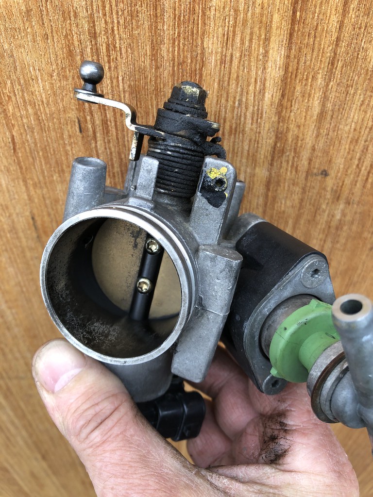
On the cable system in Programme 210 the Bowden cable sets the plate from the pedal. A motor can move that plate only in the idle range, in combination with the cruise-control system. Further torque changes use ignition timing and injection timing. Electronic power control drives the one plate over the whole travel, and the idle switch in the throttle unit is no longer required.
Workshop measurements
Read each track against its supply. Move the pedal, or the plate with the motor unpowered, and watch both tracks.
| Document | Pair | Relationship |
|---|---|---|
| Bosch Motorsport electronic throttle body, 27 January 2026 | Throttle outputs I and II | 0 to 5 V and 5 to 0 V across 0 to 90°. Sensor supply 5 V ± 0.2 V. Motor supply 6 to 16 V. |
| MS 7.8 operation manual | Main and redundant throttle voltages | Sum within 0.2 V of 5 V. Main rises, redundant falls. Accepted window about 200 mV to 4,800 mV. |
| MS 7.8 operation manual | Pedal potentiometers | First voltage minus twice the second below 0.5 V, or below UAPSCM_MAX. Accepted window about 200 mV to 4,800 mV. |
| DV-E5 customer information, 23 October 2000, counter-clockwise, new part | Dividers IP1 and IP2 | Lower mechanical stop 10% ± 4% and 90% ± 4% of the 5 V ± 0.2 V supply. Upper stop 93% ± 4% and 7% ± 4%. Ratiometric. Homokinetic tolerance ±4% of the maximum value, referenced to the potentiometer value at the lower stop. Lifetime figures at the stops widen to ±5%. |
| Volkswagen SSP 210, display group 062 | G187 with G188, and G79 with G185 | Throttle 0 to 100% against 100 to 0%. Pedal 0 to 98% against 0 to 49%. Percent of 5 V. |
The DV-E5 clockwise body has its own tolerance table. A two-to-one pedal pair and an opposite-direction throttle pair belong on different inputs. Lower-stop learning on the DV-E5 is limited to 20°/s, and the information states that the plate must not be driven dynamically into the stops. After replacement of the throttle unit, the control unit or the engine, Programme 210 requires a basic setting so the stops are stored.
Sources
- Bosch Mobility, electronic throttle valve. Names DV-E/RKL-E5.9, the motor-driven plate, Hall feedback, pedal and torque-request inputs, t90 below 100 ms, and analog or SENT. Accessed 2026-11-13.
- Bosch Mobility data sheet, electronic throttle valve DV-E/RKL-E. Bore ranges for DV-E5.2/RKL-E5.2 and DV-E5.9(E)/RKL-E5.9(E), the spring in the parts list, idle air leakage, and the same function and t90. Accessed 2026-11-13.
- Bosch Mobility, accelerator-pedal module. Pedal sensor as the torque request for electronic air-charge control, idle-voltage tolerance ±1%, sensor synchronicity below 1.5%. Accessed 2026-11-13.
- Bosch Motorsport, electronic throttle body, 27 January 2026. System of throttle body, pedal module and control unit; redundant outputs 0 to 5 V and 5 to 0 V; sensor supply 5 V ± 0.2 V; motor supply 6 to 16 V; idle default position and idle-air position. Accessed 2026-11-13.
- Bosch Motorsport MS 7.8 operation manual. Pedal two-to-one check, throttle sum and direction, 200 mV to 4,800 mV window, inactive electronic throttle, and calibration codeword 4 for the limp-home position. Accessed 2026-11-13.
- Bosch technical customer information Y 289 K00 025, DV-E5, 23 October 2000. NLP above the lower stop, 5° standard angle, return spring, 100 ms powered t90 and 300 ms currentless return, ratiometric divider ratios, 20°/s stop learning, and the 60 mm airflow. Accessed 2026-11-13.
- Volkswagen Self-Study Programme 210, Electronic Power Control, technical status May 1999. Removal of the Bowden cable, long-term charge path and short-term path, pedal and throttle redundancy, emergency running, 1500 rpm cases, display group 062, and the cable-throttle comparison. Accessed 2026-11-13.