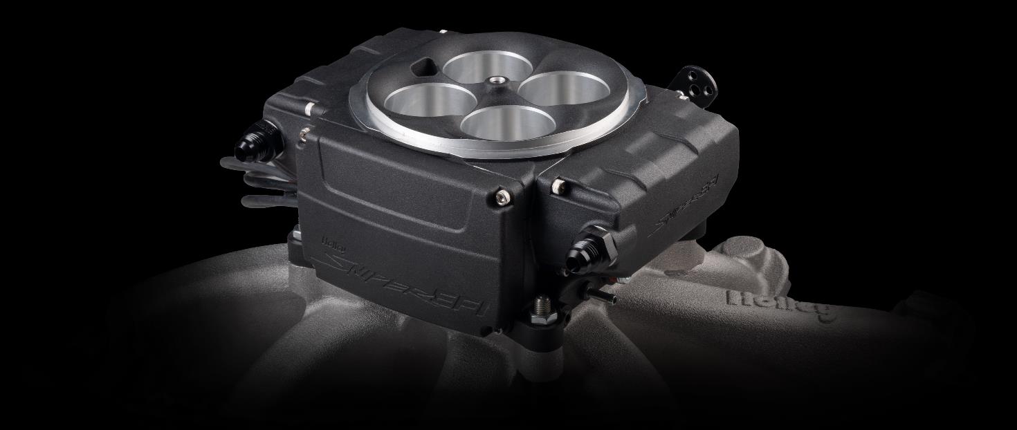
Sniper 2 is the second generation of Holley's integrated throttle-body EFI system; the ECU and throttle body are a package rather than a generic HP or Terminator module. The 550-511 product information describes updated ECU electronics and a main harness with HyperSpark distributor support.
Wiring and ignition
Holley's system installation diagrams identify a 16-pin main connector, separate CAN and six-pin optional I/O harness for the documented 550-511 arrangement. Its ignition options guide distinguishes a coil-minus RPM-only input from supported timing-control configurations. Verify the specific throttle body, harness, ignition and sensor setup.
See the Holley EFI manufacturer index. Sources reviewed 17 November 2026.
Six-way I/O harness connector
From the Holley Sniper 2 EFI QuickStart guide, for the optional 558-497 I/O harness. Outputs are ground-side relay triggers; consult the guide for current limits and configuration. This table does not document the separate 16-way main connector.
Six-way I/O harness
| Pin | Wire colour | Function |
|---|---|---|
| A | Orange | TPS output, 0–5 V |
| B | Black/yellow | Output 1, ground-switched relay trigger; default fan 1 |
| C | Light blue | Input 2, programmable ground input |
| D | Light green | Input 1, programmable ground input; default IAC kick |
| E | Grey | Tachometer output |
| F | Green/white | Output 2, ground-switched relay trigger; default fan 2 |
Sixteen-way main connector
Holley’s Sniper 2 QuickStart guide, page 6, identifies all 16 lettered positions of the main harness connection. This connector is separate from the optional six-way I/O harness above. Refer to the source for the connector orientation and the correct ignition wiring. The ECU’s ground outputs are rated at 2 A or less and are relay triggers; do not infer that the pump itself is driven directly by pin R.
| Pin | Wire colour | Holley function | Application / note |
|---|---|---|---|
| A | Red | Battery positive (+) | Connects directly to battery positive |
| B | Pink | Switched ignition +12 V | Must remain powered during cranking |
| C | Yellow | Coil negative RPM input | Engine-speed input; ignition-type dependent |
| D | Green | Crank signal negative | Engine-speed signal ground |
| E | Green/white | Output 2 (−) | Optional ground-side relay trigger |
| F | Orange | TPS output | Optional transmission-controller TPS signal |
| G | Light green | Input 1 (−) | Optional programmable ground input |
| H | Brown | CAN 2 high | Future expansion |
| J | Orange | CAN 2 low | Future expansion |
| K | Grey | Tach output | Aftermarket tachometer |
| L | Light blue | Input 2 (−) | Optional programmable ground input |
| M | Black/yellow | Output 1 (−) | Optional ground-side relay trigger |
| N | Purple | Crank signal input | Engine-speed signal input |
| P | White | Points output | Triggers a CDI ignition box |
| R | Blue | Fuel pump output (−) | Fuel-pump ground output / relay trigger |
| S | Black | Battery negative (−) | Connects directly to battery negative |
Holley identifies two distinct main harnesses: 558-190 is for an external relay or PDM, while 558-191 incorporates a fuel-pump relay and larger power wire. The downstream pump connection therefore depends on the harness; match the part number and current manufacturer guide.