RM-Primis BMW E36 M3 S50B32 MSS50 plug-in ECU is a vehicle-specific package based on the RM Racing Electronics RM-Primis standalone ECU. The manufacturer describes an application-specific adapter between the standalone controller and the original vehicle loom; the ECU and adapter are distinct components. Source: manufacturer product documentation.
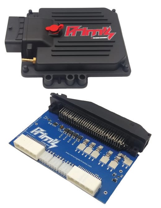
Application and installation
The manufacturer lists European-market E36 M3 S50B32 and its MSS50 original engine management. Check the actual engine, original ECU part number, connector, donor loom, immobiliser and transmission with the supplier; trim or model-year labels alone do not establish compatibility.
The seller describes an ECU plus pre-wired adapter and cable, and two-solenoid-per-cam VANOS control. Its page also mentions a Bosch 88-pin ECU; verify the original MSS50 connector and supplied adapter with the manufacturer, as nomenclature and connector configurations are application-specific.
Control and tuning
RM-Tuner provides calibration and data logging. The manufacturer describes a built-in 400 kPa MAP sensor, wideband compatibility with LSU 4.9/4.2 sensors, CAN communications, configurable safety and boost control. Electronic-throttle capability and ZF 8HP functions depend on the purchased hardware, firmware and compatible transmission. Confirm what is included before assuming an accessory or feature is present.
Connectors and wiring
The model sales page does not provide a verified complete ECU-to-adapter and vehicle-connector cavity schedule. Use the RM-Primis documentation and the exact adapter guide for the hardware supplied; do not transfer another BMW kit’s pinout based only on connector shape or model family.
References
RM-Primis BMW E36 M3 S50B32 MSS50 plug-in ECU manufacturer listing; RM-Primis universal platform; RM Racing Electronics index.
RM-Primis plug-in adapter board headers
The RM Racing booklet, PDF page 12, labels the RM-Primis plug-in adapter’s left and right 32-position board headers looking straight at the board. The generic drawing does not identify this vehicle kit; confirm that the delivered adapter has the pictured headers and matching board revision with RM before using these tables. These are board-side connector positions, not the original vehicle’s loom or ECU connector cavity numbers. Vehicle-specific adapters can route or condition signals differently; consult the model-specific auxiliary notes above and confirm the wiring before connecting devices.
Header 1 — left side of board
| Board-header position | Manufacturer function |
|---|---|
| 1 | Injector output 1 |
| 2 | Injector output 2 |
| 3 | Injector output 3 |
| 4 | Injector output 4 |
| 5 | Injector output 5 |
| 6 | Injector output 6 |
| 7 | Ignition output 1 |
| 8 | Ignition output 2 |
| 9 | Ignition output 3 |
| 10 | Ignition output 4 |
| 11 | Ignition output 5 |
| 12 | Ignition output 6 |
| 13 | Fuel pump output |
| 14 | Low-side GP 1 |
| 15 | Low-side GP 2 |
| 16 | Low-side GP 3 |
| 17 | Ground |
| 18 | Ignition-switch input +12 V |
| 19 | Permanent battery +12 V |
| 20 | LSU IP |
| 21 | LSU RCAL |
| 22 | LSU VS/IP |
| 23 | LSU VS |
| 24 | LSU H+ |
| 25 | LSU H− |
| 26 | Tachometer output |
| 27 | High-side GP 4 |
| 28 | High-side GP 3 |
| 29 | High-side GP 2 push-pull |
| 30 | High-side GP 1 push-pull |
| 31 | Low-side GP 5 |
| 32 | Low-side GP 4 |
Header 2 — right side of board
| Board-header position | Manufacturer function |
|---|---|
| 1 | Throttle position sensor input |
| 2 | Coolant temperature sensor input |
| 3 | Intake air temperature sensor input |
| 4 | Digital / trigger input 1 (pull-up selectable) |
| 5 | Digital / trigger input 2 (pull-up selectable) |
| 6 | Digital / trigger Hall input (no pull-up) |
| 7 | MAF / analogue voltage input |
| 8 | Spare voltage input 1 |
| 9 | Spare voltage input 2 |
| 10 | Spare voltage input 3 |
| 11 | Spare voltage input 4 |
| 12 | Spare voltage input 5 (pedal 2 when DBW) |
| 13 | Spare temperature input 1 |
| 14 | Spare temperature input 2 (pedal 1 when DBW) |
| 15 | DBW TPS input 2 |
| 16 | 5 V output for sensors |
| 17 | DBW motor + |
| 18 | DBW motor − |
| 19 | Ground |
| 20 | Ground |
| 21 | Ground |
| 22 | 5 V output for sensors |
| 23 | CAN low |
| 24 | CAN high |
| 25 | Knock sensor 2 − |
| 26 | Knock sensor 2 + signal |
| 27 | Knock sensor 1 − |
| 28 | Knock sensor 1 + signal |
| 29 | Variable-reluctance sensor 2 − |
| 30 | Variable-reluctance sensor 2 + |
| 31 | Variable-reluctance sensor 1 − (adjustable threshold) |
| 32 | Variable-reluctance sensor 1 + (adjustable threshold) |