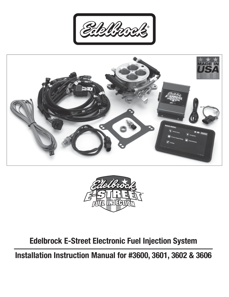
Edelbrock E-Street EFI: The first E-Street system is a carburettor-replacement throttle-body fuel-injection kit with an external ECU, harness and tablet interface. Edelbrock’s original installation manual covers 3600, 3601, 3602 and 3606 packages. These package numbers should be distinguished from E-Street 2 and EZ-Street, whose hardware and software differ.
Selection and system layout
Identify the exact ECU, engine and kit part number, intake and throttle, sensor and ignition arrangement. The phone or tablet app is the calibration and monitoring interface, not the ECU. Fuel delivery, return plumbing and auxiliary components depend on the package. Consult the manufacturer documentation for the specific configuration.
Wiring documentation
Use the model-specific Edelbrock source for hardware and wiring. The main harness schedule below is for the original E-Street packages covered by the cited manual; do not substitute another Pro-Flo or E-Street generation.
Original E-Street main harness and ECU connector
Edelbrock’s E-Street installation instructions 63-3600, revision 1, printed page 22 (PDF page 23), show the E1 34-way connector from the harness side for kits 3600, 3601, 3602 and 3606. The manufacturer’s N/C marks refer to the illustrated harness; they do not establish the function or electrical state of a different ECU or harness revision. Wire abbreviations and signal labels follow the drawing.
| E1 position | Signal | Illustrated harness wire |
|---|---|---|
| 1 | INJ A | BLK/GRN |
| 2 | 12V SW. | ORANGE |
| 3 | CURRENT LOOP TXD — N/C | — |
| 4 | LAMBDA CR1 | DK BLU |
| 5 | COOLANT TEMP | YEL/BLK |
| 6 | AIR T | TAN |
| 7 | AC SWITCH INPUT — N/C | — |
| 8 | FUEL PRESSURE | BRWN/YEL |
| 9 | MAP | GRN |
| 10 | INJ B | BLK/GREY |
| 11 | LAMBDA VS+ | BLK/ORG |
| 12 | LAMBDA IP+ | BLK/RED |
| 13 | LAMBDA IP− | BLK/YEL |
| 14 | RS232 TXD (EFI) | RED/BLU |
| 15 | RS232 RXD (EFI) | GRN/WHT |
| 16 | TPS | DK BLU |
| 17 | RPM SIGNAL (MAG or HALL) | WHT/BLK |
| 18 | INJ C | BLK/WHT |
| 19 | IAC (COIL 1A) | WHT/VLT |
| 20 | IAC (COIL 1B) | WHT/RED |
| 21 | IAC (COIL 2A) | WHT/YEL |
| 22 | IAC (COIL 2B) | WHT/BLU |
| 23 | GND | BLK/WHT/OR |
| 24 | GND | BLK |
| 25 | VREF | GREY |
| 26 | INJ D | BLK/BLU |
| 27 | RPM SIGNAL (COIL NEG) | TAN/YEL |
| 28 | MSD OUTPUT — N/C | — |
| 29 | FAN 1 OUTPUT — N/C | — |
| 30 | FAN 2 OUTPUT — N/C | — |
| 31 | LAMBDA VH− | VLT |
| 32 | FUEL PUMP 12V PWM OUT | RED/WHT |
| 33 | GND | BLK/WHT |
| 34 | BLUETOOTH ANTENNA — N/C | — |
E5 PC communications connector
Separate nine-position communications connector from the same drawing, not the 34-way ECU connector. Crossed-out positions are represented as shown in the illustrated harness.
| E5 position | Drawing label |
|---|---|
| 1 | No connect |
| 2 | TXD (PC) |
| 3 | RXD (PC) |
| 4 | No connect |
| 5 | PWR GND |
| 6 | SW +12V — crossed out / not connected on drawing |
| 7 | PWR GND — crossed out / not connected on drawing |
| 8 | No connect |
| 9 | No connect |