RM-Primis BMW M43 plug-in ECU is a vehicle-specific package based on the RM Racing Electronics RM-Primis standalone ECU. The manufacturer describes an application-specific adapter between the standalone controller and the original vehicle loom; the ECU and adapter are distinct components. Source: manufacturer product documentation.
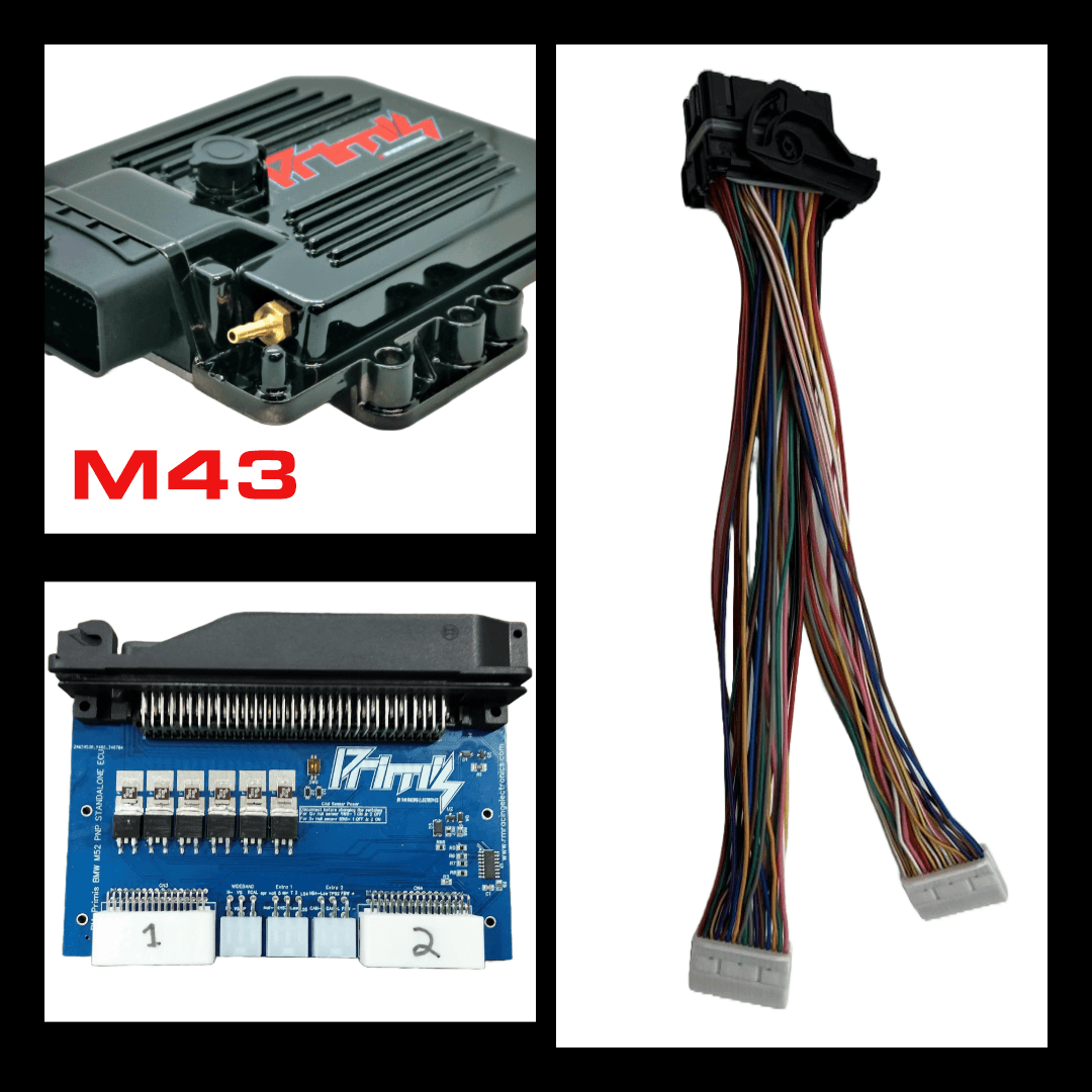
Application and installation
The manufacturer lists BMW M43 four-cylinder applications, including the listed E36 316i/318i and E34/E39 518i. Check the actual engine, original ECU part number, connector, donor loom, immobiliser and transmission with the supplier; trim or model-year labels alone do not establish compatibility.
The vendor specifies an RM-Primis ECU, an 88-pin BMW harness adapter, ECU cable and model jumpers. Confirm the original engine management and connector, especially before applying it to M43TU or a swapped loom.
Control and tuning
RM-Tuner provides calibration and data logging. The manufacturer describes a built-in 400 kPa MAP sensor, wideband compatibility with LSU 4.9/4.2 sensors, CAN communications, configurable safety and boost control. Electronic-throttle capability and ZF 8HP functions depend on the purchased hardware, firmware and compatible transmission. Confirm what is included before assuming an accessory or feature is present.
Connectors and wiring
The model sales page does not provide a verified complete ECU-to-adapter and vehicle-connector cavity schedule. Use the RM-Primis documentation and the exact adapter guide for the hardware supplied; do not transfer another BMW kit’s pinout based only on connector shape or model family.
References
RM-Primis BMW M43 plug-in ECU manufacturer listing; RM-Primis universal platform; RM Racing Electronics index.
Adapter auxiliary connectors — BMW M50/M4x and M6x 88-pin adapter
RM Racing’s RM-Primis booklet, PDF page 16, documents the following six-way accessory connector assignments for the adapter named above. These are the adapter’s auxiliary and LSU connectors, not the factory vehicle connector and not the 32-way board-to-ECU headers shown in the drawing. The source labels those larger headers by position but does not supply their per-pin functions. Match the actual adapter board and revision before using this schedule. The booklet says the two marked high-side outputs are converted on the adapter board to ground-switching outputs; select the corresponding high-side channel in RM-Tuner. Verify installed board and output ratings before connecting any load.
LSU 4.9 wideband adapter connector
| Adapter pin | Signal | Sensor wire colour | LSU 4.9 sensor pin |
|---|---|---|---|
| 1 | H− | White | 3 |
| 2 | VS | Black | 6 |
| 3 | Rcal | Green | 5 |
| 4 | H+ | Grey | 4 |
| 5 | VS/IP | Yellow | 2 |
| 6 | IP | Red | 1 |
Auxiliary connector 1
| Pin | Manufacturer function |
|---|---|
| 1 | Spare voltage input 5 |
| 2 | Spare temperature input 2 |
| 3 | Low-side general-purpose output 4 |
| 4 | MAF / analogue voltage input |
| 5 | Digital / trigger input 2 |
| 6 | Low-side general-purpose output 5 |
Auxiliary connector 2
| Pin | Manufacturer function |
|---|---|
| 1 | High-side output 4 (converted on board to low-side output) |
| 2 | High-side output 1 (converted on board to low-side output) |
| 3 | Drive-by-wire motor + |
| 4 | CAN high |
| 5 | CAN low |
| 6 | Drive-by-wire motor − |