PnPduino Universal is a PnPduino programmable engine-management ECU. Manufacturer product information.
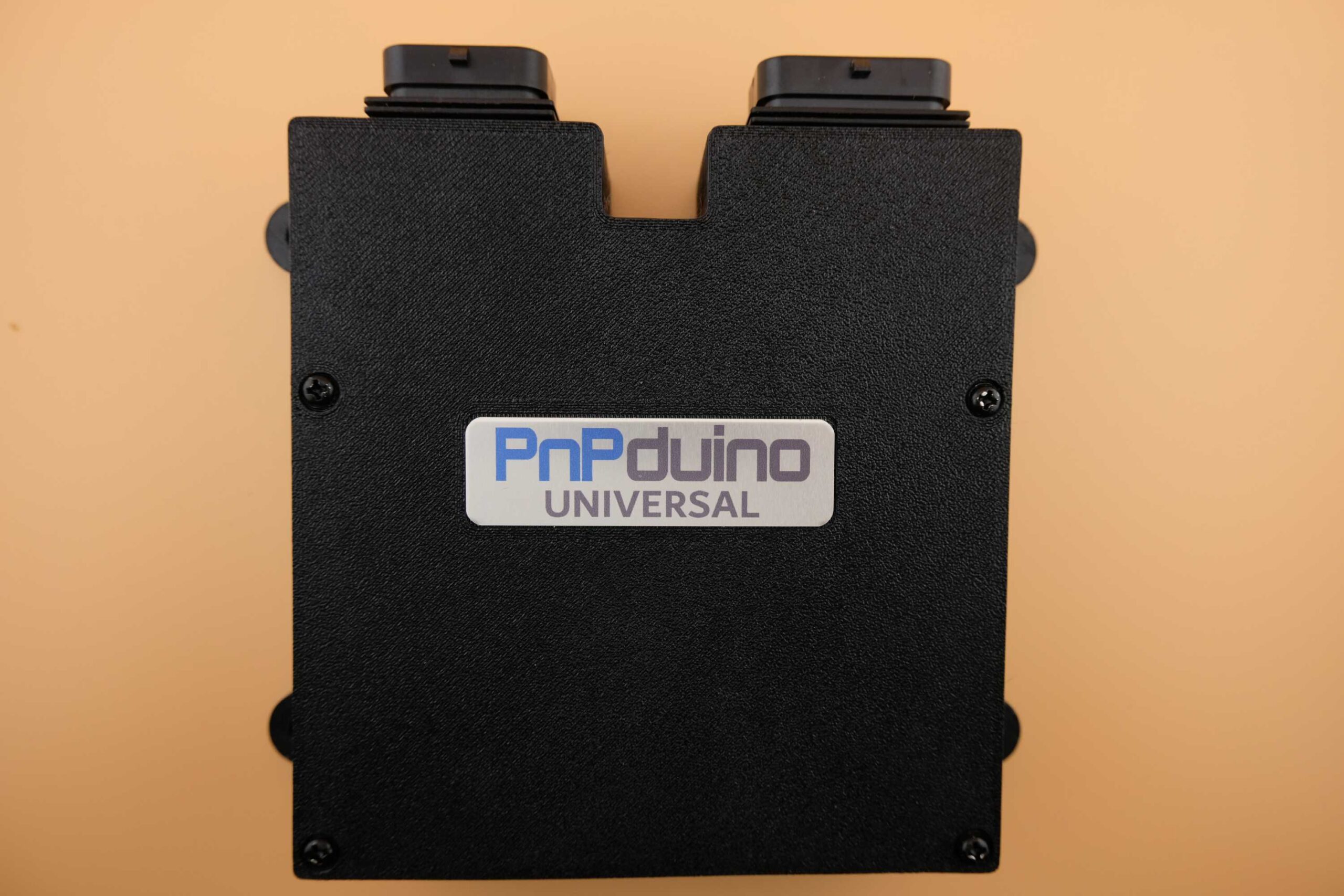
Application and identification
A configurable wire-in ECU that the manufacturer says can operate as a standalone or piggyback and supports engines up to eight cylinders. The manufacturer specifies manual transmission and cable-throttle use.
System and wiring
The input header is a 34-position AMP Superseal 1.0 three-slot connector; the output header is a separate 26-position three-slot connector. Optional components include an internal 4-bar MAP sensor, Bluetooth, VR conditioner, stepper driver and wideband. The ASA/ABS case is not waterproof and the manufacturer says to install it inside the car.
Connector identification
| Connector | Manufacturer description | Scope |
|---|---|---|
| Input header | 34 positions, AMP Superseal 1.0, three-slot | Manufacturer product listing |
| Output header | 26 positions, AMP Superseal 1.0, three-slot | Manufacturer product listing |
The manufacturer’s model-specific connector schedule is transcribed below. Confirm the hardware revision, optional equipment and calibration before wiring.
Software and calibration
The product lists TunerStudio and official Speeduino firmware. Verify outputs, sensors and firmware for the actual build and obtain the model-specific pinout before wiring.
See the PnPduino manufacturer index.
Model-specific wiring document
The manufacturer provides a 34-way input and 26-way output connector drawing. Confirm the exact firmware and unit build, and follow the drawn connector orientation. Open the PnPduino pinout document. The separate connector-identification table above is a summary; the full manufacturer-labelled schedule follows below.
PnPduino Universal manufacturer connector schedule
Transcribed from the PnPduino PnPduino Universal pinout. Follow the connector drawing in the source and verify the actual build and orientation; the source does not explicitly identify its view as ECU-face or wire-side. Arduino pins are software/board assignments, not connector cavity numbers. A blank manufacturer label is recorded as unlabelled rather than assumed unused.
A-plug input — 34 positions
| ECU pin | Manufacturer label | Manufacturer description | Arduino pin |
|---|---|---|---|
| A1 | INP4 | Spare Input 4 | A11 |
| A2 | INP1 | Spare Input 1 | A8 |
| A3 | CLT | Engine Coolant Temp | A4 |
| A4 | TPS | Throttle Position Sensor | A3 |
| A5 | O2 | Wideband O2 Sensor | A1 |
| A6 | VR2+ | VR2+ or Hall Sensor 2 | D18 |
| A7 | VR1+ | VR1+ or Hall Sensor 1 | D19 |
| A8 | 5V Out | 5V Out to sensors | — |
| A9 | 12V In | 12V Input from Ignition switch | — |
| A10 | INP3 | Spare Input 3 | A10 |
| A11 | IAT | Intake Air Temperature | A5 |
| A12 | PG | Power Ground for Wideband | — |
| A13 | PG | Power Ground | — |
| A14 | CLUTCH | Clutch Switch | 37 |
| A15 | VR2- | VR2- / Hall Sensor2 Logic Ground | — |
| A16 | VR1- | VR1- / Hall Sensor1 Logic Ground | — |
| A17 | INP5 | Spare Input 5 | A6 |
| A18 | GPI | GPI for Serial 3 Connection | 15 |
| A19 | INP2 | Spare Input 2 | A9 |
| A20 | 12V Out | Fused 12V Supply(sensors only) | — |
| A21 | 12V Out | Fused 12V Supply(sensors only) | — |
| A22 | 12V Out | Fused 12V Supply(sensors only) | — |
| A23 | 12V Out | Fused 12V Supply(sensors only) | — |
| A24 | VSS | Vehicle Speed Sensor | 20 |
| A25 | INP7 | Spare Input 7 | A13 |
| A26 | EXTMAP | External MAP sensor | A0 |
| A27 | GPO | GPO for Serial 3 Connection | 14 |
| A28 | FLEX | Flex Fuel Sensor | 2 |
| A29 | HALL4 | Hall Sensor 4 | 3 |
| A30 | GRND | ECU Ground | — |
| A31 | GRND | Power Ground | — |
| A32 | GRND | Sensor Ground | — |
| A33 | HALL3 | Hall Sensor 3 | 21 |
| A34 | INP6 | Spare Input 6 | A12 |
B-plug output — 26 positions
| ECU pin | Manufacturer label | Manufacturer description | Arduino pin |
|---|---|---|---|
| B1 | VVT | VVT/VVTI or VTEC/VTC terminology | 11 |
| B2 | IDLE2 | Idle 2 or Spare High Current 1 | 10 |
| B3 | IDLE1 | Idle 1 for IACV Solenoid | 9 |
| B4 | INJ4 | Injector 4 | 5 |
| B5 | INJ3 | Injector 3 | 6 |
| B6 | INJ2 | Injector 2 | 7 |
| B7 | INJ1 | Injector 1 | 8 |
| B8 | BOOST | Boost or Spare Hi Current 2 | 12 |
| B9 | LC3 | Low Current Output 3 | 28 |
| B10 | LC2 | Low Current Output 2 | 27 |
| B11 | LC1 | Low Current Output 1 | 26 |
| B12 | FAN | Radiator Fan 1 | 24 |
| B13 | Not labelled in source | ~Not Connected~ | — |
| B14 | IGN4 | Ignition Output 4 | 34 |
| B15 | IGN3 | Ignition Output 3 | 33 |
| B16 | LC4 | Low Current Output 4 | 29 |
| B17 | Not labelled in source | ~Not Connected~ | — |
| B18 | FAN2 | Fan 2 or Spare Low Current Output | 25 |
| B19 | TACH | Tachometer Output 5V or 12V | 22 |
| B20 | IGN1 | Ignition Output 1 | 35 |
| B21 | IGN2 | Ignition Output 2 | 36 |
| B22 | STP-B2 | Stepper Idle Air Coil B2 | — |
| B23 | STP-B1 | Stepper Idle Air Coil B1 | — |
| B24 | STP-A1 | Stepper Idle Air Coil A1 | — |
| B25 | STP-A2 | Stepper Idle Air Coil A2 | — |
| B26 | FUELP | Fuel Pump or Circuit Opening Relay | 23 |
The source states that ignition outputs are 5 V, not 12 V; IDLE2 and BOOST can be used as high-current outputs and FAN2 as a low-current output. The manufacturer distinguishes ECU, power and sensor grounds from chassis ground; follow its wiring instructions.