Removed text is struck through; added text is highlighted.
Haltech Nexus Plug-in Honda EP3 2001–2005 and DC5 2002–2004 is a vehicle-specific, direct plug-in programmable ECU, Haltech part HT-231001, that replaces the original engine ECU. Haltech product listing.Haltech Nexus Plug-in Honda EP3 DC5 2001–2004 is a vehicle-specific, direct plug-in programmable ECU, Haltech part HT-231001, that replaces the original engine ECU. Haltech product listing.
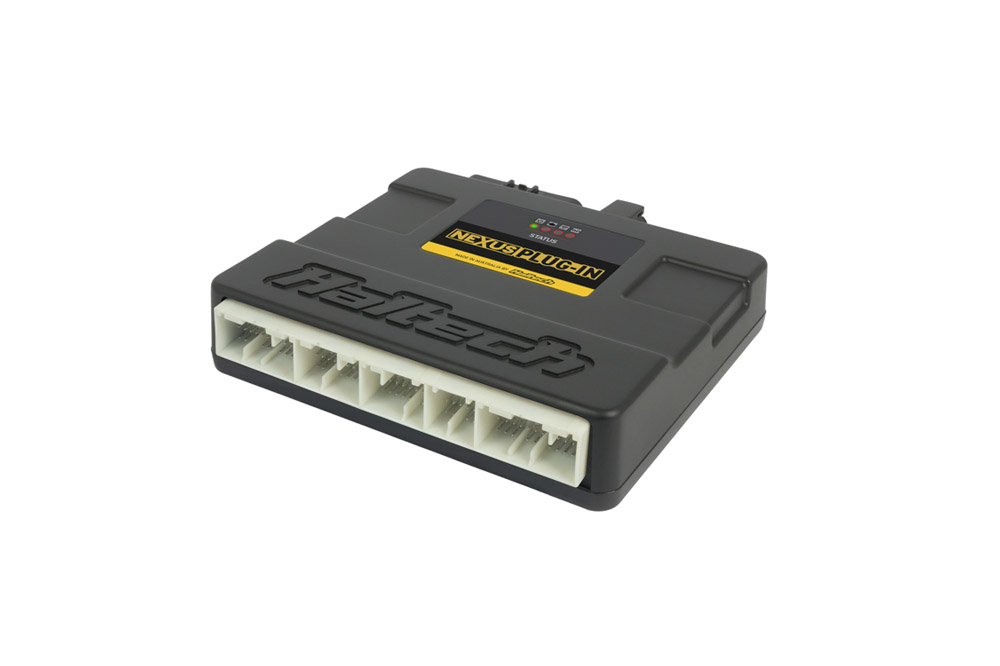
Haltech Nexus Honda plug-in ECU. The same manufacturer photograph appears on the EP3 and DC5 product listings; confirm the part number and connector application. Haltech product photograph, reproduced with permission.
Applications and identification
The HT-231001 is listed by Haltech for the 2001–2005 Honda Civic EP3 and 2002–2004 Honda Integra / Acura RSX DC5, manual transmission only. The manufacturer says a K24A swap is supported when the original vehicle engine harness is retained for the correct pin assignments.
Haltech says the original four-wire wideband sensor is not supported and calls for an LSU 4.9 or NTK sensor via the auxiliary connector. The ECU has an onboard 4-bar MAP sensor; its vacuum connection must be connected if used. Manufacturer details are in the Honda Nexus installation guide.
Vehicle connector assignments
These 86 assignments reproduce the Haltech 231001 quick-start guide, PDF page 7, manufacturer document hosted by a retailer. View is the ECU pin side; Haltech marks vehicle connectors C and D unused. Use the chart for this exact part number; calibratable outputs depend on setup.
The manufacturer schedule lists both E1 and E10 as DPO 11 fuel-pump relay output; verify the vehicle harness and the current manufacturer documentation if using these circuits.
The following table is the ECU auxiliary connector, pin-side view, from the same manufacturer guide, page 8. It is distinct from the vehicle ECU connectors above. Haltech states switched 12 V from the onboard CAN and auxiliary connectors is limited to 8 A total across the three pins.
Nexus Software Programmer (NSP) configures and tunes the ECU; USB-C and optional Wi-Fi communication are described in Haltech’s installation guide. The setup wizard provides a starting configuration and the engine requires appropriate tuning.
Rendered revisions
Open each version to inspect formatting, tables and photographs.
Haltech Nexus Plug-in Honda EP3 DC5 2001–2004 is a vehicle-specific, direct plug-in programmable ECU, Haltech part HT-231001, that replaces the original engine ECU. Haltech product listing.
Haltech Nexus Honda plug-in ECU. The same manufacturer photograph appears on the EP3 and DC5 product listings; confirm the part number and connector application. Haltech product photograph, reproduced with permission.
Applications and identification
The HT-231001 is listed by Haltech for the 2001–2005 Honda Civic EP3 and 2002–2004 Honda Integra / Acura RSX DC5, manual transmission only. The manufacturer says a K24A swap is supported when the original vehicle engine harness is retained for the correct pin assignments.
Haltech says the original four-wire wideband sensor is not supported and calls for an LSU 4.9 or NTK sensor via the auxiliary connector. The ECU has an onboard 4-bar MAP sensor; its vacuum connection must be connected if used. Manufacturer details are in the Honda Nexus installation guide.
Vehicle connector assignments
These 86 assignments reproduce the Haltech 231001 quick-start guide, PDF page 7, manufacturer document hosted by a retailer. View is the ECU pin side; Haltech marks vehicle connectors C and D unused. Use the chart for this exact part number; calibratable outputs depend on setup.
The manufacturer schedule lists both E1 and E10 as DPO 11 fuel-pump relay output; verify the vehicle harness and the current manufacturer documentation if using these circuits.
Vehicle connector A
Pin
ECU connection
Manufacturer function
A1
Unused
No connection
A2
+12V ECU power
ECU switched power supply
A3
+12V ECU power
ECU switched power supply
A4
Power ground
Battery ground
A5
Power ground
Battery ground
A6
Unused
No connection
A7
Trigger
Crank sensor
A8
AVI 12
Dual intake runner position input
A9
Knock 1
Knock sensor
A10
Sensor ground
Sensor ground
A11
Sensor ground
Sensor ground
A12
DPO 6
Idle control
A13
Unused
No connection
A14
Unused
No connection
A15
AVI 10
Throttle position sensor
A16
Unused
No connection
A17
Unused
No connection
A18
SPI 5
Vehicle speed sensor
A19
AVI 9
MAP sensor
A20
+5V DC
+5V sensor supply
A21
+5V DC
+5V sensor supply
A22
Unused
No connection
A23
Power ground
Battery ground
A24
Power ground
Battery ground
A25
SPI 6
Intake cam sensor
A26
Home
Exhaust cam sensor
A27
Ignition 4
Ignition output for cylinder 4
A28
Ignition 3
Ignition output for cylinder 3
A29
Ignition 2
Ignition output for cylinder 2
A30
Ignition 1
Ignition output for cylinder 1
A31
Unused
No connection
Vehicle connector B
Pin
ECU connection
Manufacturer function
B1
HBO 3
Intake VTC solenoid control
B2
Injector 4
Injector output for cylinder 4
B3
Injector 3
Injector output for cylinder 3
B4
Injector 2
Injector output for cylinder 2
B5
Injector 1
Injector output for cylinder 1
B6
DPO 10
Thermofan relay output
B7
DPO 8
Reverse lockout solenoid
B8
AVI 8
Coolant temperature sensor
B9
AVI 13
Oil pressure switch (VTEC)
B10
AVI 16
Alternator L
B11
Unused
No connection
B12
Unused
No connection
B13
AVI 17
Alternator FR
B14
Unused
No connection
B15
HBO 4
VTEC solenoid
B16
Unused
No connection
B17
AVI 7
Intake air temperature sensor
B18
DPO 17
Alternator control output
B19
Unused
No connection
B20
Unused
No connection
B21
DPO 12
Evap purge valve solenoid
B22
DPO 5
Dual intake runner system (IMRC)
B23
Power ground
Battery ground
B24
Unused
No connection
Vehicle connector E
Pin
ECU connection
Manufacturer function
E1
DPO 11
Fuel pump relay output
E2
AVI 6
Narrowband O2 sensor input
E3
Power ground
Immobilizer ground
E4
Sensor ground
Sensor ground
E5
+5V DC
+5V sensor supply
E6
DPO 7
O2 sensor heater output
E7
ECR
Engine control relay output
E8
Unused
No connection
E9
Ign SW Input
Ignition switch
E10
DPO 11
Fuel pump relay output
E11
Unused
No connection
E12
Unused
No connection
E13
Unused
No connection
E14
AVI 14
Fuel tank pressure sensor
E15
AVI 15
Electrical load detector input
E16
AVI 11
Power steering switch input
E17
Unused
No connection
E18
DPO 14
A/C relay output
E19
Unused
No connection
E20
DPO 16
Evap bypass solenoid
E21
DPO 13
Evap vent shut valve
E22
AVI 5
Brake pedal switch input
E23
Unused
No connection
E24
Multiplex serial comms
Multiplex serial communications
E25
Unused
No connection
E26
DPO 15
Tachometer output
E27
Immobilizer comms
Immobilizer serial communications
E28
Unused
No connection
E29
Unused
No connection
E30
Unused
No connection
E31
DPO 9
Check engine light
26-pin auxiliary connector
The following table is the ECU auxiliary connector, pin-side view, from the same manufacturer guide, page 8. It is distinct from the vehicle ECU connectors above. Haltech states switched 12 V from the onboard CAN and auxiliary connectors is limited to 8 A total across the three pins.
Pin
Haltech connection
Harness colour
1
DPO 1
Violet / Blue
2
DPO 3
Violet / Red
3
Aux power (12V switched)
Red
4
Sensor ground
Black / White
5
SPI 1
Gray / Brown
6
SPI 3
Gray / Orange
7
HBO 1
Brown / Black
8
AVI 1
White
9
AVI 3
White / Gray
10
Sensor ground
Black / White
11
WBI 1 Heater +
Gray
12
WBI 1 Input
Yellow
13
WBI 1 Pump
Red
14
DPO 2
Violet / Brown
15
DPO 4
Violet / Orange
16
Aux power (12V switched)
Red
17
Sensor +5V DC
Orange
18
SPI 2
Gray / Red
19
SPI 4
Gray / Yellow
20
HBO 2
Brown / Red
21
AVI 2
White / Yellow
22
AVI 4
White / Violet
23
Sensor +5V DC
Orange
24
WBI 1 Nernst
Black
25
WBI 1 Heater -
White
26
WBI 1 Cal
Green
Software
Nexus Software Programmer (NSP) configures and tunes the ECU; USB-C and optional Wi-Fi communication are described in Haltech’s installation guide. The setup wizard provides a starting configuration and the engine requires appropriate tuning.
Haltech Nexus Plug-in Honda EP3 2001–2005 and DC5 2002–2004 is a vehicle-specific, direct plug-in programmable ECU, Haltech part HT-231001, that replaces the original engine ECU. Haltech product listing.
Haltech Nexus Honda plug-in ECU. The same manufacturer photograph appears on the EP3 and DC5 product listings; confirm the part number and connector application. Haltech product photograph, reproduced with permission.
Applications and identification
The HT-231001 is listed by Haltech for the 2001–2005 Honda Civic EP3 and 2002–2004 Honda Integra / Acura RSX DC5, manual transmission only. The manufacturer says a K24A swap is supported when the original vehicle engine harness is retained for the correct pin assignments.
Haltech says the original four-wire wideband sensor is not supported and calls for an LSU 4.9 or NTK sensor via the auxiliary connector. The ECU has an onboard 4-bar MAP sensor; its vacuum connection must be connected if used. Manufacturer details are in the Honda Nexus installation guide.
Vehicle connector assignments
These 86 assignments reproduce the Haltech 231001 quick-start guide, PDF page 7, manufacturer document hosted by a retailer. View is the ECU pin side; Haltech marks vehicle connectors C and D unused. Use the chart for this exact part number; calibratable outputs depend on setup.
The manufacturer schedule lists both E1 and E10 as DPO 11 fuel-pump relay output; verify the vehicle harness and the current manufacturer documentation if using these circuits.
Vehicle connector A
Pin
ECU connection
Manufacturer function
A1
Unused
No connection
A2
+12V ECU power
ECU switched power supply
A3
+12V ECU power
ECU switched power supply
A4
Power ground
Battery ground
A5
Power ground
Battery ground
A6
Unused
No connection
A7
Trigger
Crank sensor
A8
AVI 12
Dual intake runner position input
A9
Knock 1
Knock sensor
A10
Sensor ground
Sensor ground
A11
Sensor ground
Sensor ground
A12
DPO 6
Idle control
A13
Unused
No connection
A14
Unused
No connection
A15
AVI 10
Throttle position sensor
A16
Unused
No connection
A17
Unused
No connection
A18
SPI 5
Vehicle speed sensor
A19
AVI 9
MAP sensor
A20
+5V DC
+5V sensor supply
A21
+5V DC
+5V sensor supply
A22
Unused
No connection
A23
Power ground
Battery ground
A24
Power ground
Battery ground
A25
SPI 6
Intake cam sensor
A26
Home
Exhaust cam sensor
A27
Ignition 4
Ignition output for cylinder 4
A28
Ignition 3
Ignition output for cylinder 3
A29
Ignition 2
Ignition output for cylinder 2
A30
Ignition 1
Ignition output for cylinder 1
A31
Unused
No connection
Vehicle connector B
Pin
ECU connection
Manufacturer function
B1
HBO 3
Intake VTC solenoid control
B2
Injector 4
Injector output for cylinder 4
B3
Injector 3
Injector output for cylinder 3
B4
Injector 2
Injector output for cylinder 2
B5
Injector 1
Injector output for cylinder 1
B6
DPO 10
Thermofan relay output
B7
DPO 8
Reverse lockout solenoid
B8
AVI 8
Coolant temperature sensor
B9
AVI 13
Oil pressure switch (VTEC)
B10
AVI 16
Alternator L
B11
Unused
No connection
B12
Unused
No connection
B13
AVI 17
Alternator FR
B14
Unused
No connection
B15
HBO 4
VTEC solenoid
B16
Unused
No connection
B17
AVI 7
Intake air temperature sensor
B18
DPO 17
Alternator control output
B19
Unused
No connection
B20
Unused
No connection
B21
DPO 12
Evap purge valve solenoid
B22
DPO 5
Dual intake runner system (IMRC)
B23
Power ground
Battery ground
B24
Unused
No connection
Vehicle connector E
Pin
ECU connection
Manufacturer function
E1
DPO 11
Fuel pump relay output
E2
AVI 6
Narrowband O2 sensor input
E3
Power ground
Immobilizer ground
E4
Sensor ground
Sensor ground
E5
+5V DC
+5V sensor supply
E6
DPO 7
O2 sensor heater output
E7
ECR
Engine control relay output
E8
Unused
No connection
E9
Ign SW Input
Ignition switch
E10
DPO 11
Fuel pump relay output
E11
Unused
No connection
E12
Unused
No connection
E13
Unused
No connection
E14
AVI 14
Fuel tank pressure sensor
E15
AVI 15
Electrical load detector input
E16
AVI 11
Power steering switch input
E17
Unused
No connection
E18
DPO 14
A/C relay output
E19
Unused
No connection
E20
DPO 16
Evap bypass solenoid
E21
DPO 13
Evap vent shut valve
E22
AVI 5
Brake pedal switch input
E23
Unused
No connection
E24
Multiplex serial comms
Multiplex serial communications
E25
Unused
No connection
E26
DPO 15
Tachometer output
E27
Immobilizer comms
Immobilizer serial communications
E28
Unused
No connection
E29
Unused
No connection
E30
Unused
No connection
E31
DPO 9
Check engine light
26-pin auxiliary connector
The following table is the ECU auxiliary connector, pin-side view, from the same manufacturer guide, page 8. It is distinct from the vehicle ECU connectors above. Haltech states switched 12 V from the onboard CAN and auxiliary connectors is limited to 8 A total across the three pins.
Pin
Haltech connection
Harness colour
1
DPO 1
Violet / Blue
2
DPO 3
Violet / Red
3
Aux power (12V switched)
Red
4
Sensor ground
Black / White
5
SPI 1
Gray / Brown
6
SPI 3
Gray / Orange
7
HBO 1
Brown / Black
8
AVI 1
White
9
AVI 3
White / Gray
10
Sensor ground
Black / White
11
WBI 1 Heater +
Gray
12
WBI 1 Input
Yellow
13
WBI 1 Pump
Red
14
DPO 2
Violet / Brown
15
DPO 4
Violet / Orange
16
Aux power (12V switched)
Red
17
Sensor +5V DC
Orange
18
SPI 2
Gray / Red
19
SPI 4
Gray / Yellow
20
HBO 2
Brown / Red
21
AVI 2
White / Yellow
22
AVI 4
White / Violet
23
Sensor +5V DC
Orange
24
WBI 1 Nernst
Black
25
WBI 1 Heater -
White
26
WBI 1 Cal
Green
Software
Nexus Software Programmer (NSP) configures and tunes the ECU; USB-C and optional Wi-Fi communication are described in Haltech’s installation guide. The setup wizard provides a starting configuration and the engine requires appropriate tuning.